How to install the app on iOS
Follow along with the video below to see how to install our site as a web app on your home screen.
Note: This feature may not be available in some browsers.
Largest Manufacturing Technology Community on the Web
Stay Connected:
You are using an out of date browser. It may not display this or other websites correctly.
You should upgrade or use an alternative browser.
You should upgrade or use an alternative browser.
need help wiring an Arco phase converter
- Thread starter Scotty J
- Start date
- Replies 15
- Views 12,861
I would assume it is pretty much the same as the smaller ones...... I have an MF, yours is presumably an "A".
There is an installation guide on the Arco website.
http://www.arco-electric.com/InstallationGuide.cfm
I have a manual for the "MF" which may have a relevant diagram in it, but I have no scanner, and would have to probably scan it at work, or take a picture of it.
Edit: I see that a link to the Arco diagram has been provided. The installation instructions are elsewhere on the site and have that at the bottom..
They also provide fusing info, expected current readings, etc.
For the Model "A", if that is what you have, your 8 Ga is right, 30A fuse, no load line amperage is 4, capacitor amperage is 22. You can check those numbers as an initial check of operation.
If your load blows the fuse, it could be the load, or it could be that you have excess current in teh RPC for some reason. Check the line and capacitor currents with a clamp-on meter.
ToughTool
Hot Rolled
- Joined
- Apr 9, 2007
- Location
- Panama City, Florida 32401
Scotty j
jst's link should be enough to show you how to wire your Arco. However I'm not sure of your problem. Your other post indicates you have a problem with your load. Is your unit wired like the sample schematic in the referenced link, or is the problem starting the RPC idler and connecting the load motor?
I noticed the Arco sample schematic does not have a start capacitor shown. Without a momentary phase shift to the third leg of the idler motor, you will need to get the idler shaft to near speed some other way before you apply single phase power to motor leads A and C. The magnetic starter in the Arco schematic looks to me like one that is used to start a 3 phase motor from 3 phase power. An application that seems wrong to me here. However it could be only used for it's heaters; in other words, to protect the motor(s). 3 phase motors running on 3 phase power do not need a starting capacitor, just connection to the three lines, A, B, and C, usually with a magnetic starter. That is why you can instantly reverse any two of the 3 phase lines and the motor will reverse without stopping first. You can't do that with the typical single phase motor. (excluding ceiling fan motors and those like them)
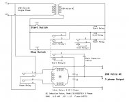
Here is my schematic using a simple manual Push and Hold [till idler is at speed] Start Switch (for about 1 second) that is somewhat typical of RPC wiring schemes. Capacitors C1 and C2 are only used if you are balancing your idler's outputs. Also if the power relay (with large contacts) has three contact sets, the Hold relay can be eliminated by using the power relay's third contact as the Pick and Hold contact (hold relay-1). My 50 amp power relay, connecting power to the idler motor, only had two contact sets. Therefore two control relays were needed. Joe
jst's link should be enough to show you how to wire your Arco. However I'm not sure of your problem. Your other post indicates you have a problem with your load. Is your unit wired like the sample schematic in the referenced link, or is the problem starting the RPC idler and connecting the load motor?
I noticed the Arco sample schematic does not have a start capacitor shown. Without a momentary phase shift to the third leg of the idler motor, you will need to get the idler shaft to near speed some other way before you apply single phase power to motor leads A and C. The magnetic starter in the Arco schematic looks to me like one that is used to start a 3 phase motor from 3 phase power. An application that seems wrong to me here. However it could be only used for it's heaters; in other words, to protect the motor(s). 3 phase motors running on 3 phase power do not need a starting capacitor, just connection to the three lines, A, B, and C, usually with a magnetic starter. That is why you can instantly reverse any two of the 3 phase lines and the motor will reverse without stopping first. You can't do that with the typical single phase motor. (excluding ceiling fan motors and those like them)
Here is my schematic using a simple manual Push and Hold [till idler is at speed] Start Switch (for about 1 second) that is somewhat typical of RPC wiring schemes. Capacitors C1 and C2 are only used if you are balancing your idler's outputs. Also if the power relay (with large contacts) has three contact sets, the Hold relay can be eliminated by using the power relay's third contact as the Pick and Hold contact (hold relay-1). My 50 amp power relay, connecting power to the idler motor, only had two contact sets. Therefore two control relays were needed. Joe
Attachments
Scotty j
Is your unit wired like the sample schematic in the referenced link, or is the problem starting the RPC idler and connecting the load motor?
I noticed the Arco sample schematic does not have a start capacitor shown. Without a momentary phase shift to the third leg of the idler motor, you will need to get the idler shaft to near speed some other way before you apply single phase power to motor leads A and C. The magnetic starter in the Arco schematic looks to me like one that is used to start a 3 phase motor from 3 phase power. An application that seems wrong to me here.
Does not apply....
The Arco is self-starting..... The capacitor is permanently internally connected, it is an oil-filled start/run/balance capacitor. It can be seen by looking in the wiring box (sometimes, depending on HP, "it" may be "they")
If you look on the installation guide, you will see the "capacitor current" reading I referred to. That reading will check the proper value and operation of the start/run/balance capacitor.
I use a standard motor starter to run mine.... it starts in under 1 second and works perfectly.
ToughTool
Hot Rolled
- Joined
- Apr 9, 2007
- Location
- Panama City, Florida 32401
jst,
OK. Didn't have access to the installation guide but it makes sense. So the "Starter" (customer supplied item) is probably referenced to provide the start and stop buttons and control circuit to pick the contactor (high current relay) so the motor can start, stay "ON", until the Stop button is pressed or power failure occurs. I guess I should get one of those Steveco 90-66 potential relays to make my starting circuit automatic.
In the meantime, we wait for Scotty j to give us an update. Joe
Rick.H
Plastic
- Joined
- Sep 28, 2023
- Location
- Horseheads, NY
Hello, I'm new to the forum and also have an ARCO Electric, Roto Phase Generator 5 HP and a model 2. I'm trying to wire it up to run my Hardinge HLV. In reading the link above to the ARCO website for an installation guide was not useful...sorry. Now the attached drawing (jpg) was helpful and have a further question on this.
According to the picture of the wires, there is a wires labeled B (red), E (green), and T1, T2 & T3 all black. So my understanding is to supply 220 single phase to the B and E wires. Use the T1, T2 and T3 (generated leg) to supply the 3 phase to my lathe. Does this sound right?
According to the picture of the wires, there is a wires labeled B (red), E (green), and T1, T2 & T3 all black. So my understanding is to supply 220 single phase to the B and E wires. Use the T1, T2 and T3 (generated leg) to supply the 3 phase to my lathe. Does this sound right?
Attachments
![20230928_144355[1].jpg](/forum/data/attachments/351/351093-0dcb191bf2e4b56bb04c1f5712457e48.jpg)
![20230927_164311[1].jpg](/forum/data/attachments/351/351094-6eda6edaae182999a16ceb088e7f6206.jpg)
duckfarmer27
Stainless
- Joined
- Nov 4, 2005
- Location
- Upstate NY
Hello, I'm new to the forum and also have an ARCO Electric,
Rick -
All my documentation is out in the shop and I have not had to mess with mine in a few years. I have a 20 HP and can't remember the model. Just checking their web site the documentation does not seem to be posted like it used to be. I did have good luck talking to one of their application engineers years ago - but JST and others on here were who really bailed me out tuning it.
Having said all that - do you have a box with capacitors that came with the motor unit? Every ARCO I've seen has a capacitor box with it.
I'll look up some of my documentation the next day or two. Interesting you live in Horseheads - I'm 18 miles east of you.
Rick.H
Plastic
- Joined
- Sep 28, 2023
- Location
- Horseheads, NY
Duck Farmer,
Thank you for your reply. Here is a picture inside the box. It looks like I hook up 220 single phase to the E and B wires. T1 thru T3 are 3-phase outputs. I'm trying this today. This is in concert with the attached diagram above. I'll try it with my breaker switch for a moment and see if it starts. I'll be sure to use a good ground. We'll let you know.
Rick
Attachments
![20230929_151356[1].jpg](/forum/data/attachments/351/351487-2e235174b61f639ccc6b1cf697be3faf.jpg)
rons
Diamond
- Joined
- Mar 5, 2009
- Location
- California, USA
I suggest you Arcolytes make a electrical drawing with all part-to-part wire connections.
You can trace each wire one at a time then mark it with a piece of tape, keep doing this until all wires have a tape marker.
Display picture here and get your notepad ready.
You can trace each wire one at a time then mark it with a piece of tape, keep doing this until all wires have a tape marker.
Display picture here and get your notepad ready.
duckfarmer27
Stainless
- Joined
- Nov 4, 2005
- Location
- Upstate NY
Rick -
I looked earlier today and was going to reply. After seeing your post from this morning Ron beat me to it. I hope you slow down a bit - don't mean to insult you but how much wiring have you done? Just 'hooking up' and 'try it with my breaker switch to see if it starts' when dealing with equipment is not a real good idea. Admittedly I'm a cautious retired mechanical engineer and soldier who had life safety responsibility at different career points.
My message to you was going to be you must have a newer model than what I have documentation for. So I was going to suggest a call to ARCO tomorrow - ask for the application engineering area. You really need the data on what you have. From the picture you posted this morning I THINK I can see what is going on. However, I'm going to defer to Ron as he's more expert than I am in this area. Like he suggested, come up with a wiring diagram - and if you did as you proposed early today be VERY careful as poking around those capacitors could give you some real excitement when you start discharging them with your body.
Like my one buddy and I remind each other at times - 'As Clint Eastwood said, a man has to know his limitations'.
Stay safe
Rick.H
Plastic
- Joined
- Sep 28, 2023
- Location
- Horseheads, NY
Hi Everyone,
I figured it out and posting here for future inquires. The first attachment is the wiring of my ARCO Roto Phase Converter. Like I mentioned above, 5 wires are sticking out the wire box. The insides are shown. Next attachment is the wiring to get the Roto running correctly. It took me 3 tries to get it right. Last attachment is the wiring in my shop to get 3-phase power to my Hardinge HLV, The lathe runs very smooth and responsive. The only down side is that the Roto is a little loud. I'll try putting a sound deadening box around it while keeping ventilation. It does go quieter when the lathe is running.
Thanks for all the help.
Kind regards,
Rick
Attachments
Generally, the wires that are the input wires will NOT be the pair that has a capacitor across them.
If the unit has one capacitor, like mine, the correct pair will be one that connects to the capacitor directly, and one that does not.
For one with double capacitors such as the OP has, the pair that are input will be the two that each connect to only one capacitor. The generated leg will connect to both capacitors directly.
You may need to use an ohmmeter to decide which wire is directly connected, if there are no markings on the wires.
Last edited:
rons
Diamond
- Joined
- Mar 5, 2009
- Location
- California, USA
The reduction in noise when the lathe runs indicates a more balanced mode. Measure voltages T1 to T2, T1 to T3, T2 to T3.
Image(84).jpg has no magnetic contactor.
There is a wide range when it comes to "running". It runs now or how does it run now. What are the capacitor values?
Image(84).jpg has no magnetic contactor.
There is a wide range when it comes to "running". It runs now or how does it run now. What are the capacitor values?
Last edited:
rons
Diamond
- Joined
- Mar 5, 2009
- Location
- California, USA
If you can use a relay to disconnect the start capacitor your RPS would be quieter.
I use a relay to switch out 120uF from a 210uF total of start capacitance on L3 to L2.
That leaves me with a 90uF and a 50uF for run caps on a 5 Hp RPC.
I use a relay to switch out 120uF from a 210uF total of start capacitance on L3 to L2.
That leaves me with a 90uF and a 50uF for run caps on a 5 Hp RPC.
Donald Hansen
Plastic
- Joined
- Sep 27, 2004
- Location
- Maine
Here's something I picked and used for my rotophaseCan someone please explain to me how to correctly wire an Arco 5hp. rotary phase converter. I would like to use a magnetic stater to start the converter along with a main disconnect switch. Thanks Scotty J.
Attachments
Hi, I'm new to the forum and also have an ARCO Electric Roto-Phase. (Model R) Recently acquired at auction. There are rumors on this forum and other places online that there is an installation guide but I have tried all the links and can find them nowhere on Kirbyrisk/ Acro-Electric where I get redirected. Does anyone have a copy they could post? I'll probably have questions later but I always read what I can first before diving in. Thanks.
Similar threads
- Replies
- 1
- Views
- 616
- Replies
- 13
- Views
- 235
- Replies
- 12
- Views
- 694
- Replies
- 41
- Views
- 903