What's new
What's new

Phase Converter Idle Motor Issue - Hard Shutdown

Speedracer983

Plastic
Joined
Jun 27, 2017
Following for years, first time poster, thanks for taking the time to help.

In the process of prepping my home shop for some 3PH equipment (Saw, Mill and Lathe )

The rotary phase converter that I am running is a 7HP system taken out from a buddies home shop. Unfortunately he had minimal knowledge and just removed everything leaving it in a pile.

The system is wired ( to the best of my ability ) and working, generating 3PH power. My issue is when I shut the system down, with no load, meaning no machines are creating a draw, the idle motor makes a noise like it is receiving stray voltage and drastically reduces speed then coast to a stop in 5 or so seconds.

My buddy said it never did that and always "softly" shutdown, coasting to a stop in 30 to 45 seconds. I have gone over the wiring options several times with no luck. A tough question with my less than ideal explanation but any direction offered would be greatly appreciated.

Its a typical rotary system with 50A feed, traditional start and run capacitors, switching relay and a 7HP Baldor idle motor.
 
It sort of sounds as if the start circuit is cutting in and putting a load on while the thing is still generating. Normally when it is shut down, it stops generating. With a lot of capacitance in place, it can actually generate with no AC connection, though.

What are you doing to shut down, just killing input power?

Can you provide any sort of wiring diagram?
 
That would make sense .... As the system drops it hits a point and the start capacitors dump trying to restart ? If I am thinking of that correctly.

Yes, to shut the system down I am killing the inlet power with a rotary disconnect.

I'll work up a diagram to illustrate the system.

Ultimately there are two legs feeding A & C legs in my 3ph pannel.

The idle motor is connected to A, B & C legs

The capacitor and relay circuit pull feed from the C leg and return on the B leg.

Start and run capacitors are run in two banks respectively through the relay.

One thing I just noticed, I have an indicator light tied into the relay to indicate the system is running, as if the motor noise wasn't enough. Upon shutdown the light turns off, on then off in coordination with the mystery load. It appears the capacitors are dumping through the relay into the system.

How can I rewire to eliminate the capacitor feed on shutdown ? Clearly this is wrong and I don't want to hurt the motor or capacitors.
 
Also possible that the start capacitors are keeping a charge on them. When the start relay closes on shutdown (normal), if there is a charge on the capacitors, that will do the same as a DC braking system, which is fairly aggressive braking.

You cure that by putting resistors "across" the capacitor terminals to drain off the charge. You should have them anyway, for safety, you do not want to go in there to fix something with the power off and get a zap from a charged-up capacitor..

The usual electrolytic types don't hold a charge well, but if someone uses the motor-run type for start duty, they hold a charge quite well. Either type needs the resistors.
 
I'll work up a diagram to illustrate the system.

We need that. Narrative text doesn't DO well for circuit layout unless all-hands are looking at the same info to begin with.

As to a 'fix', first see JST's note on bleeder resistors, and then...

..so long as the sequence of events is not damaging a(ny) switch, relay or caps, 1 or 2 seconds would be overly-aggressive braking, but this is a rather small RPC as such things go.

Accordingly, there really isn't a lot "wrong" with an idler that slows to a stop in 5 seconds instead of 45 seconds.

Most especially if it was DIY'ed with an exposed, keyed, shaft that could snag a trouser leg, impact a broom or length of stock being carried about or such.

Lazy Iyam - I just provided a cheap metal wastebasket to cover mine rather than cut the shaft short on an idler I might want to return to service as an ordinary motor someday. A length of ignorant iron pipe on a large "floor flange" could be better ... if/as/when I get a 'round tuit'. McMaster-Carr stocks those, do they? Got everything else, so...

:)
 
It's just guess work until a schematic is shown. :scratchchin:

The coasting time depends on the RPM of the idler. For example, my 5hp 1725 takes a little over 60 seconds to stop.
 
The capacitors are in a secondary box within the relay housing but I agree they should be made safer by adding resistors.

Do I need to add one to each individual capacitor or just one within each series, start and run respectively ?

It's strange to me that this was wired in such a manner previously that this was not an issue but if adding resistors are a solution I'm all for it.

Thanks for the help.

I'll mark up a diagram in the morning and figure out how to post it on the thread.
 
Last edited:
You will be adding RESISTORS to the existing capacitors, IF YOU NEED THEM..... AND WE DO NOT KNOW THAT YET.

Until we see the schematic or wiring diagram, we have NO IDEA what you have there, and it is then all guesswork as to what is wrong.

So DO NOT rush out and get resistors, show us what you have for wiring first. Might be some totally different thing going on.
 
Betcha that series =parallel in this case......

Setup looks reasonable, reading between the lines to some extent. Probably the resistors are the issue.

Does seem odd that there are many more run caps than start caps.... A picture might be good to eliminate any questions.
 
My apologies, 220V

Regarding the capacitors, I am not sure exactly what you mean but each bank ( run and start respectively ) have a different number of capacitors. The info on them has been removed so I do not know what electrical value they have, they could possibly have the same output value. I only know how many each series ( which may be a poor term to use) or bank has count wise.

From what I can tell the bank of 6 is active at all times when the system is running, the bank containing 2 drops out after startup via the relay opening.

One point that was mentioned by a buddy was that I am feeding the wrong side of the relay. The coil terminal should receive power from L1 or L2 .... I have it connected to B which is the generated leg. I do not know if that will make a difference.
 
If the relay is a potential relay then how do you think they are supposed to work? The generated voltage is what controls the switch action.

Any multimeter these days has a capacitance range. Measure your banks.
 
I guess I'm learning here Rons ..... The relay is a potential relay so it would need a signal feed to operate.

Excuse my ignorance but how would the capacitor values have anything to do with them feeding back during shutdown ? Aside from the missing resistors I think it's a circuit issue rather than a component issue. Everthing I was able to test checks out.

I changed the wiring on the relay and the generated voltage will trigger the coil off of either lug as long at the start capacitor circuit is on the non-coil lug.

I want to add that this whole unit is somewhat of a commercial unit produced by a local shop, Phelps Electronics. Unfortunately the owner passed away some years ago and the company closed down.
 
OK....

"Parallel" is when there are a series of capacitors, each with two terminals, and one set of wires connect to all the "left hand" terminals, while the other set connects to all the "right hand" terminals. Two wires connect each capacitor and the next one.

"Series" is where a wire goes to the "left hand" terminal of the first capacitor, and another comes from the "right hand" terminal to go to the next capacitor, and so on. Only one wire goes between each capacitor and the next one.

pictures of all the parts, preferably from at least two angles in places where there is wiring, will help and avoid all sorts of questions.
 
OK....

"Parallel" is when there are a series of capacitors, each with two terminals, and one set of wires connect to all the "left hand" terminals, while the other set connects to all the "right hand" terminals. Two wires connect each capacitor and the next one.

"Series" is where a wire goes to the "left hand" terminal of the first capacitor, and another comes from the "fight hand" terminal to go to the next capacitor, and so on. Only one wire goes between each capacitor and the next one.

pictures of all the parts, preferably from at least two angles in places where there is wiring, will help and avoid all sorts of questions.

And all sorts of answers.
 
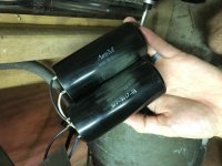
Taking photos that would make any kind of sense is near impossible, the system is spread across three cabinets. Here are photos of the capacitor banks. As you can see most identifying info has been removed from all components. IMG_0789.JPGIMG_0790.JPGIMG_0791.jpg
 
As you can see most identifying info has been removed from all components.

That is because the builder has to keep his trade secret from being exposed. Loose lips sinks ships.... :gossip:

We will respect his patent rights. It must have something to do with his proprietary scheme for wire color coding. By the way, all your capacitors are connected in parallel.

I suspect the potential relay (if that is what you have) is faulty. One reason I don't use them.


Back
Top