What's new
What's new

Questions on Yaskawa V1000 drive

Randalthor

Cast Iron
Joined
Mar 7, 2018
Location
Kansas City
I ended up buying a single phase V1000 drive for my 2J 1-1/2 Bridgeport mill.

CIMR-VUBA0010FAA - Yaskawa - AC Drives | Galco Industrial Electronics

I'm new to VFD's but have read the quick start manual (200+ pages).

https://www.galco.com/techdoc/yask/v1000_qs.pdf

I have some questions please, for anyone familiar with these drives.

1. I assume I want the control mode as Open Loop Vector, instead of V/f for a Bridgeport mill?

2. How fast can I safely stop the motor without any damage to the motor/head. My understanding is that there is a built in braking feature on this VFD. Of course the mill has a mechanical brake built in the head, but if I can stop the motor with the braking feature of the VFD, that would be a nice feature. I just don't how fast one can safely stop it over and over, without damage.

3. At the end of the manual (page 201) it suggests a 50A input fuse for this drive. This seems ridiculous to me, as the wire recommended is #12, plus the drive doesn't pull anywhere near 50 amps. I'm sure I'm misunderstanding something. Can someone please clarify?

I'm sure I'll have more questions as I move forward, but any help on any of these questions would be appreciated.
 
1. Yes, I would use sensorless vector setting, you get much better control of speed and power, in particular at lower Hz.

2. Braking is a function of momentum in the system, and braking time is dependent on if you use an external braking resistor (which I recommend). You can get a generic braking resistor for $40-50, the resistance value and wattage is dependent on the VFD model/voltage. On my 3Hp mill I have it set a 3 seconds stopping time. There is much more momentum in the system when using the back gear, so 3 seconds is a reasonable balance. One can use two different braking rates, so if something like the E-Stop was engaged you could get shorter braking times if desired. Acceleration is 5 seconds.

3. Breaker size is usually 125% of the VFD rating. I have the BA0012 VFD on my mill and run 30A fast blow CC fuses with no issues on single phase. Other VFD manufactures, 30-40A is a typical fuse size for 2 and 3 Hp VFDs. There is some variation depending on the fuse type and if it is a dual element or high speed. Typically cartridge fuse holders use a larger holder for anything above 30A. Breakers may be sized slightly larger than the fuse size, but I still would use something like a 30 or 32A breaker for a 2 Hp single phase VFD. My 2Hp lathe VFD runs off a 20A breaker and I have never tripped it and run the vector motor to 200% overload for short periods.
 
Thanks mksj. You mention a braking resistor is preferred. Is that just because it stops faster, or is there some other reason? Btw, am I correct that the VFD has a built in stop, which somehow uses the motor to stop itself?

I also had a question about the output terminals - MA, MB, MC. The manual labels them as Multifunction Digital output. The output is 30 VDC with up to 1 amp. Does anyone know what these terminals are used for? I've looked through the manual and that's the only description given.
 
When you are stopping a VFD, a braking resistor dissipates the excess regenerative energy into the resistor for quicker stopping. Most VFDs have the internal circuity and a braking resistor, but it is limited in capacity. By adding an external resistor it can dissipate much more energy, but there is a limit beyond which the VFD will go into an over voltage error and free wheel to a stop. An external braking resistor is inexpensive, but some of the cheaper VFDs are missing the braking circuity to support an external braking resistor or require an expensive proprietary braking module.

The Multifunction Digital output is a trigger output that can be programmed to be switched for different triggers (typically a fault situation). Parameters H2-01, H2-02 and H2-03 assign functions to digital output terminals MA, MB, MC, P1, and P2. Set these parameters as required by the application. The switch rating is 10 mA to 1A.
 
I might actually suggest, for you as new to VFDs, to just use V/F mode for a bit. It's not really "simpler" from your side of the control panel, but there are fewer "details", it is a bit more straightforward, fewer possible surprises to confuse you.

Nobody stops you from swapping over to vector any time you want, if you find that you do not get what you want from the setup..
 
When you are stopping a VFD, a braking resistor dissipates the excess regenerative energy into the resistor for quicker stopping. Most VFDs have the internal circuity and a braking resistor, but it is limited in capacity. By adding an external resistor it can dissipate much more energy, but there is a limit beyond which the VFD will go into an over voltage error and free wheel to a stop. An external braking resistor is inexpensive, but some of the cheaper VFDs are missing the braking circuity to support an external braking resistor or require an expensive proprietary braking module.

The Multifunction Digital output is a trigger output that can be programmed to be switched for different triggers (typically a fault situation). Parameters H2-01, H2-02 and H2-03 assign functions to digital output terminals MA, MB, MC, P1, and P2. Set these parameters as required by the application. The switch rating is 10 mA to 1A.

Thanks. The reason I asked about MA, MB, MC is that I bought a lightly used box (actually I don't think it's ever been used, just a little scuffed paint) for the VFD off ebay, which has a couple nice filtered inlets, with one small 24VDC fan on one of the inlets. According to the fan specs, the fan can run up to 28VDC.

I was considering trying to run the fan off the MA, MB, MC terminals (recognizing the output would actually be a couple volts higher - and hoping that wouldn't produce magic smoke from the fan).

As I write this, it's sounding less of a good idea. I generally try to do stuff by the book, and respect the specs, but it would be nice to be able to run the fan off the VFD.

KIMG0934[1].jpg
 
The VFD requires the KW value of the motor during setup. The motor nameplate doesn't list the KW value. Does anyone know the KW value of a 1-1/2 hp motor for a 2J Bridgeport.
 
750W/Hp x 1.5Hp = 1.1kW
The digital outputs are not powered, if you need to run an external fan I typically use a separate DIN rail 24VDC power supply. The fan runs continuously or if you desire you can get an inexpensive thermostat. I use fairly quiet low speed ball bearing fans (like ADDA) with filters, barely know they are on. They typically take ~0.5A @ 24VDC.
 
The digital outputs are not powered,

Oh, OK, got it. I see now that's what you were trying to tell me before. Little confused because I'm new to the terminology. Thanks for having patience and repeating your answer.

And thanks for all the help you've given me (from advice on buying it to answering all these questions). I'm waiting for a rain day to have some time in hooking it up.
 
I hooked up the VFD today and ran across a few issues.

1. During setup one of the parameters to set up was the d1-01 frequency reference. The manual was unclear to me what this should be set at, or what is even meant by "frequency reference"? I went ahead and set it at 60, but I don't know if that's right.

2. After doing the rotational fine tuning with the VFD, I ran the mill with it. But I was unable to adjust the frequency from 60 hz. In other words, I couldn't speed up or slow down the motor. Is this related to the frequency reference question above?

3. One of the parameters was to key in the full load amps of the motor. The motor nameplate shows 4.4 amps at 230v. I assume that's the "full load" amps?
 
E1-05 is the motor voltage = 230V
E1-06 is the base frequency = 60 Hz
E1-08 is mid output frequency = 13.8V
E1-13 is the base voltage = 230V
E2-01 is the motor rated current = A; name plate full load value
E2-04 is the number of motor poles = 4 for a 1750 RPM motor
E2-03 is the motor no load current = A; usually listed on the motor plate or spec sheet. This may also be detected through motor tuning.
E2-11 is the kW of your motor

On the speed control, you do not indicate the source of the speed control, are you having problems entering it from the panel or using a remote speed pot.
See Section 3.9 Main frequency Reference in the manual and Section 5.2 Setup b1 mode of operation
If using +V, A1 and AC with an external speed pot then DIP Switch S1 needs to be set to V for a voltage source.

You also need to set the frequency reference source per section 4.6
B1-01 = 1, analog inputs A1 and A2 provide the frequency reference. If set to 0 the default it is the LED operator
B1-02 = 1, sets the drive parameters from the digital input terminals

D1-01 through D1-16 should be = 0.00, these are for Multi-Step Speed Operation Parameters for setting digital fixed frequencies.
 
Thanks mksj.

For the test run, I was just using the local operator to run the drive. No speed pot or remote switching hooked up yet. I haven't had a chance to adjust the parameters you mention yet.

Could you explain to me what they mean by "frequency reference"? Do they simply mean the output frequency sent to the motor (like 60hz, or 1/2 speed 30hz, etc.)? I understand the difference between the AC frequency and the carrier frequency, but don't know what they mean by "frequency reference".

Also, do you have a specific manufacturer you'd recommend for a 24vdc power supply for the cooling fan attached to my filtered inlet in the box? It doesn't need to be a very big power supply. The little fan obviously pulls less than 1 amp at 24v.
 
The frequency reference is just the desired frequency for the motor to run at, so the motor base frequency is 60Hz name plate, but the operational frequency may be something like 20-80 Hz for a standard 3 phase motor, my mill has a vector motor so its speed range is 20-200 Hz. You need to set up the VFD to know the source of the frequency reference it is to use, there are directions for how to use the control panel vs an external speed pot. I recommend using a small pod mounted to the mill head with 3 wire control and a speed pot.

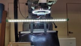
On the fan, just about any power supply will do. I suggest something like the Meanwell HDR-60-24, MDR-60-24, NDR 75-24 or the Automation Direct Rhino power supplies like the PSB24-060-P. I often add LED lighting using a light bar and Halo ring light, if 12 VDC just get an inexpensive DC to DC step down converter.

Mill LED Lighting.jpg


Back
Top