What's new
What's new

Removing an Allen Bradley 506 disconnect and relay box?

Frizzen

Aluminum
Joined
Nov 4, 2017
Hi all...my first post to this forum. Been reading it for a few months now. Little back ground on me...I have no machinest back ground but have an interest in it. I retired last year and have since picked up a 13 inch 6 foot SB lathe, went through it, also a Bridgeport mill and also went through it. I was really not looking for the mill it just came up locally so I bought it.

To my question. The same place I got the mill also had an Oliver 300HD Ace so I took it also, although I know very little about them. it has this Allen Bradley box on it and I would like to remove it, it was set up for 460V and is proving to be a pain to get changed over to 230V. I can’t get the motor running putting power through the box. I have been talking to the people at Oliver, very good and helpful people by the way, but have not had any luck getting it running. I ask them if I could just put a forward reverse switch on it, like a Bridgeport has, but they don’t like the idea. So, out of frustration, today I ran a wire from the 300 motor to the Bridgeport switch, I unhooked the bridgeport motor so it can not run. I can run the 300 in both forward and reverse using the Bridgeport switch. My question is...what problems will I have if I get a Bridgeport F/R switch and run it that way by-passing the Allen Bradley completely?
 
An AB 506 combination starter is a desirable thing to have on a machine tool. One of the best starters made. It shouldn't be too hard to make it work on low voltage.

It provides the reversing function as well as the motor overload protection. Normally all that is required to change voltage is. Reconnect the control transformer for low voltage and replace the three heater elements to larger ones for the lower voltage which is higher current. And maybe a set of fuses.

Show us what your working with, and we can steer you. A photo of the starter and the motor tag should suffice.

SAF Ω
 
Thanks for the reply. Here are the pictures you requested. I have other if you need them. One plate is the motor the other is the transformer. I reconfigured the motor and obviously it works with the mill switch. The transformer is also reconfigured. Testing voltage at any two lines I get 230V. I also changed the W34 heaters for W42’s. When I try to start the motor with the forward button is all I get is a humm.
Hope I did this reply correctly while trying to figure out how to post.
Again...thanks,
Bob Warren
E9822A44-5444-4060-A62A-6A2FB33AE8A4.jpg
3478EB56-64D3-45F5-A5A2-838DFEDAC959.jpg062DCF1C-24E2-4E45-814B-614BC93849B3.jpg

246EA554-AABD-4B4B-A350-431B0E39E574.jpg
 
I would say yes. I should have been clearer, it’s not the motor trying to start.
 
The sound is more a humm not a buzzing or clicking like a relay trying to engage.
There is no solid click like contactor closing.
 
Yeah, it sounds like the transformer taps are set wrong. You're not getting the 120V AC that the contactors need to pull in.
 
Looks like the transformer tag you posted id for an externally mounted one, with a cover.

In the lower right corner is the one that comes with the starter. Did you reconfigure that one? It has links to rearrange for the input voltage.

Buzzing of the starter magnet is an indication of low voltage in the control circuit. Half the voltage if the jumpers have not been moved.

The added external transformer may be for something added to the tool.

The fuses on the top of the control transformer may need to be changed for the lower voltage. Show what you have on the lower right control transformer connections and fuses.

SAF Ω
 
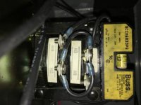
Ok, this is making sense! Oliver told me the red a white wires are 120v wires. Said to check voltage between the two, just like home wiring. I checked the upper left wires and they are 120. But I did check the wires at the unit, in the lower right, you are talking about and they are 60v. So I would say you have it. Now how do I change it? I attached a picture took yesterday of the top of the internal transformer.
A14A3B03-BFDD-4B7E-B2B2-5CA4E80349E0.jpg
 
Follow the schematic. For 480V incoming power, the transformer coils are wired in series. For 240V incoming, they are wired in parallel. Just move the jumpers to follow the schematic for 240V.
 
Got it, I could not see the schematic, it was on the side against the box wall. I got my camera in there and got the attached picture. Looks like I unhook the wires and connect H1 and H3 together and H2 and H4 together? Can’t thank you enough for the help!

I will reconfigure it in the morning and see if it works.

8CBD7BED-CBA9-40E8-B5A5-774FE318C989.jpg
 
Check the fuse verses the VA rating of the unit, they may need attention.

SAF
 
Glad to hear you got it sorted out. It would be a pity to replace that starter with a drum switch.

SAF Ω


Back
Top