What's new
What's new

Rotary phase converter rebuild help needed

bearanddragon

Plastic
Joined
Apr 27, 2017
I recently acquired an American Rotary ADX25 for parts or repair and I plan on repairing it to power my laser. The panel housing was pretty banged up and the internal components were knocked around pretty good. The guy I bought it from is trustworthy (I think)and said its complete and that the damage is just cosmetic. That being said, most the wiring on the caps was removed or pulled off when the damage occurred. I want to get this thing up and running however I can't seem to find any pictures of an ADX25 internals online anywhere. I was hoping that if someone on the forum had one and could snap a picture of its internals for me it'd be greatly appreciated. Apparently it's something that American Rotary won't release.

Thanks!
 
If not a ADX25 anyone have something close in HP from American Rotary? I'm tearing whats left of my hair out trying to figure out how to wire this thing up. Thanks!
 
If you posted some photos of what your working with, you might get some help....

SAF Ω
 
The orange and white pairs connect to the start caps.
The inner pair of start caps is missing the white wire, and needs re-connection.

The outer row of start caps needs orange and white wires connected, similar to the inner row.
Only 2 caps should be connected on a pair of wires, like the inner row, jumpers are required on one set of caps.

If the spade connectors are stretched so that they are not firm when reconnecting them they should be replaced.
Loose connections will cause them to fail during use, high starting currents, and prevent the idler from starting quickly as it should.

The rest looks intact, but do check the connections on all of the caps. Replace any connectors that are loose from the damage incurred.

SAF Ω
 
The important part is the lower half of the picture. Take some closeups from each side.

Get a little education on drawing electrical parts and then make a neat drawing of the connections. Label what the component part numbers are. At this point you cannot trust anything. Of course, you could take some answers from one of the answers above or following this one and try for a quick fix. It's better to be 100% sure when dealing with circuits.

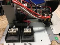
The two blocks on the left labeled L1 and L2, do you know what that means?
The three blocks on the right labeled T1,T2,T3, do you know what that means?

Input power on the left, motor/load connections on the right.
Who knows if all five start caps where connected, 2 might be spares.
 
That's true. I'm not sure if there are excessive start and/or run caps. How do I figure out how many I need for a 25HP idler? Here are some more pictures of the board. Thank you all for your help on this.
IMG_1423.jpg
IMG_1424.jpg
IMG_1425.jpg
IMG_1426.jpg
IMG_1427.jpg
 
I do have access to the setup instructions for wiring the panel and the idler motor but apparently American Rotary likes to keep their capacitor wiring schemes secret.

Thanks again!
 
Here is a picture of what I have.
View attachment 197516

Take a close up (top view) picture of just the bottom of this picture.
And verify that those 2 red wires and 3 white wires at the left side are indeed disconnected.

It does look like that the relay at the bottom is dedicated for the start operation.
It does look like the double terminal labeled T3 is for the idler/target motor connection point.
It does look like the 2nd row of start caps (from the left) do not have a common white wire connection to the start relay. So I was thinking that the third white wire from the left should be connected to the white connection on the 2nd row of start caps.
It does look like those three disconnected start capacitors on the far left need to be connected. Having those values printed on all the cans will verify that.
It does look like that input power is connected to L1 & L2. Idler motor is connected to T1,T2, & T3. Verify with your setup instructions.

I still think you would get all you want answered by making a neat drawing and labeling the values for the run/start capacitors.
It looks like all you need to do is make sure about those loose wires (red and white) on the left and connect a idler motor.
 
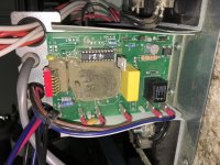
Looking at the pic, it appears that the contactor is used for starting only. I do not know if there is a voltage relay anywhere, The thing in the middle could be a VR or a timer from what I can see of it (not much).

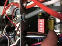
Plus, there is a PC board seen edge-on, with a TO-220 device, and what appears to be a row of dip switches. That could be a timer or voltage sensing setup. Probably not a soft-start. Wires from it seem to go to the contactor. May not be important to worry about what it does as long as it is working.
 
I forgot to include these two pictures. I'm working on drawing up the schematic as well. The start caps are 270-324 MFD and 330 VAC, the run caps are 100 MFD and 370 VAC

IMG_1429.jpg
IMG_1430.jpg
 
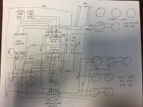
I apologize for the poor schematic. A lot of wires in there to account for. I think everything is in its place except the caps.
Image (1).jpg
 
You missed the connections on the two run capacitors, lower right, second row up.

The "dead ends" should be connected to the floating start caps, white & red, as the other ones.

Power in at the top.

Idler motor connected at the bottom.
 
Oops you're right. Should be black wires. Is there a source where I can find out if the wires are on the start and run caps in the correct order or does it matter if they're wired in parallel, in series or by themselves. Can I have too much capacitance for my 25 HP idler motor? I just need to get three phase 230 Volts out of the converter for my Laser.
 
Take the third white wire from the left and connect it to second start cap from the left, bottom row.
Connect the other white two wires to the far left start caps (left side connector on the cap)
Connect the red wires to the far left start caps (right side connector on the cap)
Now you have only the top far left start cap unconnected. Make couple of jumpers (red and white) and connect them to the far left row.

It's obvious that if there were absolutely no more wires to connect the last start cap then it was a spare. Connect it if needed.

(It's obvious where the wires should go by just looking at their lengths).


Back
Top