What's new
What's new

RPC balancing

shandit66

Aluminum
Joined
Jan 5, 2011
Location
Toronto
My apologies in advance, because I know this has been asked before.
I've read back through quite a few thread trying to figure this out, but my lack of knowledge of electrical stuff is impeding me. I need the moron's version. :) sorry

BTW - I would hire someone, but this is way out in the country and I haven't been able to find anyone.

I installed a WNY 5 hp converter and motor. ran that for a while, then needed to upgrade to 10 hp. so I bought the bigger panel

10 Hp Phase Control Panel

Diagram here: Rotary Phase Converter Control Diagram

Since shipping a 10 hp motor to Canada is expensive, I sourced one locally.
10 hp, 3ph, 3450 rpm.

Hooked it all up identical to the previous one and...lo and behold ...it works!

However: my VFD's are complaining and the various front panel buttons stop working after a while.

On advice I checked the voltages, at the RPC panel: I get 235 for 2, but 260 for one.

The suspicion is that the imbalance is bothering the VFDs.
Ok, but now how do I balance this out?

Can someone please guide me?
Unfortunately, finger puppets might be necessary. :)

Thanks
Olaf
 
Which one is high?

When ONE is high and two are equal, it looks like the input is high and the generated leg is lower. Doesn't have to be that. Your VFDs may be complaining about the one high phase.

So tell us which leg is high. Is it incoming voltage, or one of the pairs that includes the generated leg?

Due to other commitments I got massively sidetracked. My apologies.
Last weekend I finally had a chance to do some measurements which are

L1 to C, which is red,
L2 to A, which is white
B, which is black


BA - 270 = generated
AC - 234
BC - 250 = generated

Any help I can get to balance these out is really appreciated. (And I'll get back quicker now)
IMG_0948.jpg
IMG_0949.jpg

In the mean time I also found a transformer for sale, for $250.
Its 3 ph and supposedly use to balance out the legs. Not sure how that works or if its a good solution.
 
I am assuming that is with the thing basically unloaded? Usually they are not that high.

If so, my initial reaction is that it is probably over-balanced.

The "balance" capacitors act to raise voltage (and correct for RPC idler motor inductance), so long as they are not too big. So too much of a good thing raises it too far, especially if unloaded, or nearly so, VFDs on idle equal a no-load situation.

What happens when you put a significant load on it?
 
Is this with your load on ? I guess not...
So you have a RPC feeding a VFD feeding what ?


JP

Thats running a 3 hp grinder - no VFD. There a couple other machines w/o VFD: drill press, table saw
Yes, the RPC is feeding 3 different VFDs: lathe, bandsaw, blower

The biggest load will be a 7.5 hp blower - but thats not operational yet so I can't get reading with that.
 
If that is with 3HP load, you may be very much over-compensated. I would expect the 270V to begin to make many VFDs unhappy, since the high line normal limit on a 240V line is 264V, and you are over that. May be even more over that with actually NO load.

Balance is not that important unless you are trying to get full power from a load. Then you do want good balance. It is possible to attach some of the balance parts to the loads that neeed them, so that you only apply them as needed.

The basic principle here is that you use the capacitive impedance (reactance) to cancel out the inductive impedance of the motor. If done to excess, you resonate the capacitor and inductance, which may raise the voltage quite high at no load, depending on circuit parameters that we do not know. here.

It's better to be low in balance than high, as high can cause more troubles. Looks like there may be two balance parts, if you take out one (disconnect it), what happens?
 
If that is with 3HP load, you may be very much over-compensated. I would expect the 270V to begin to make many VFDs unhappy, since the high line normal limit on a 240V line is 264V, and you are over that. May be even more over that with actually NO load.

Balance is not that important unless you are trying to get full power from a load. Then you do want good balance. It is possible to attach some of the balance parts to the loads that need them, so that you only apply them as needed.

The basic principle here is that you use the capacitive impedance (reactance) to cancel out the inductive impedance of the motor. If done to excess, you resonate the capacitor and inductance, which may raise the voltage quite high at no load, depending on circuit parameters that we do not know. here.

It's better to be low in balance than high, as high can cause more troubles. Looks like there may be two balance parts, if you take out one (disconnect it), what happens?

Sorry for the questions, this is new for me.
So you suspect its the high voltages that are bothering the VFDs. I assume its outside of the accepted parameters. The manual doesnt tell me any max/min voltages.

1 - What part would you suggest I disconnect?
2 - would the above mentioned transformer make sense in order to balance this? Apparently it was used to balance out the legs, 230 in 208 out. I understand step up or down. But not how a transformer will balance between the legs.

Olaf
 
VFDs for 230V range voltages will not like anything much higher than 264V MAXIMUM. How much they accept is a matter of the detailed specifications.

Since you are probably overcompensated, the answer is likely to be disconnecting part of the balance capacitor setup. Show a picture of the entire box.... I suspect the silver-colored tubular capacitors are for balance, not starting, since they are generally smaller values and higher voltage than starting capacitors. A good picture will allow deciding who is what.

Probably the start capacitors are black plastic cased parts. Does it have some of those?
 
The big silver cans are run/balance capacitors. (You have not really shown us the full picture of your RPC panel) on the side of the run capacitors there should be a size in microfarads/MFD or µF. How many microfarads do you have on your red leg and how many do you have on your black leg? You might just have too much.

When the RPC is turned off, you have a little jumper jumping one run capacitor to another in your first picture. Pull that black lead off, start RPC and test again with maybe a cumulated 5 hp load at Idle. You might find you've gone the other way and have lower voltages. The big problem is VFD's don't like to high of voltages coming from RPC . But the rest of your inductive loads do, most RPCs are balanced to 50-75% of idler. You might have to invest in a handful of smaller run capacitors and hook them up in each machines electrical box(JST already mentioned this). Fine-tuning a RPC to make VFDs happy, sucks. This is why I like buying single phase VFD's.

Right now I am in talks with the VFD manufacture in producing a better VFD for single phase. I just got a 5hp prototype two weeks ago, and I'm happy! And I don't say that very easily. They're presently testing, The 15 hp requirement that I asked them for. In my industry this is kind of unheard of. I kind of like to keep my vFD's on single phase in my single phase environment.
 
Last edited:
The big silver cans are run/balance capacitors. (You have not really shown us the full picture of your RPC panel) on the side of the run capacitors there should be a size in microfarads/MFD or µF. How many microfarads do you have on your red leg and how many do you have on your black leg? You might just have too much.

This is the unit that I'm using:
Rotary Phase Converter Control Diagram
It commercial and unchanged.

When the RPC is turned off, you have a little jumper jumping one run capacitor to another in your first picture. Pull that black lead off, start RPC and test again with maybe a cumulated 5 hp load at Idle. You might find you've gone the other way and have lower voltages. The big problem is VFD's don't like to high of voltages coming from RPC . But the rest of your inductive loads do, most RPCs are balanced to 50-75% of idler.

The 50-75%,does that refer to the motor size? Its a 10 hp panel and 10 hp motor.
The largest single load is the 7.5 hp blower. The only machines I'm likely to run concurrently is the lathe (at low load) and the blower.

You might have to invest in a handful of smaller run capacitors and hook them up in each machines electrical box(JST already mentioned this). Fine-tuning a RPC to make VFDs happy, sucks. This is why I like buying single phase VFD's.

Right now I am in talks with the VFD manufacture in producing a better VFD for single phase. I just got a 5hp prototype two weeks ago, and I'm happy! And I don't say that very easily. They're presently testing, The 15 hp requirement that I asked them for. In my industry this is kind of unheard of. I kind of like to keep my vFD's on single phase in my single phase environment.

I had earlier also mentioned a balancing transformer:
"230 Volt MARCUS, 3 phase 15 KVA Transformer, made in Canada 100% copper, used to balance each leg of a 3 phase requirement when the legs are not equal balance for warranty on your machine. This was used on a large European printing press"

Does this seem like a solution? Its definitely easier for me than fussing with capacitors.
 
It doesn't really matter which way you go, you're going to have to fuss with something. Right now you're probably balanced perfect for your blower. So you turn your blower on check voltages then turn on one of your VFD's at the same time and it trips becauseof low voltages. The same thing would happen if you use a buck boost transformerbut in reverse. If you balance using a transformer first turn on the 7 1/2 hp blower your voltages are going to be way low.
 
It doesn't really matter which way you go, you're going to have to fuss with something. Right now you're probably bounce perfect for your blower. So you turn your blower on check voltages then turn on one of your VFD's at the same time and it trips because of low voltages. The same thing would happen if you use a buck boost transformer but in reverse. If you balance using a transformer first turn on the 7 1/2 hp blower your voltages are going to be way low.

Now I'm getting a headache.... :)

So the only thing that really creates a major sustained load is the Blower - 7.5 hp, not sure of the amps yet. But it will get used about 10% of the time.

The rest is much lower

- Grinder - 3 hp
- Table saw - 3 hp
- drill press - 2 hp
- bandsaw - 3 hp.

- lathe - 5 hp but really only draws much when doing heavy cuts. Since its a wood lathe and I'm a one man shop, its hard to measure the voltage at the panel at the same time. :)

Most of these will not be run concurrently.
(Ok - I'll leave the lathe running as I sharpen chisels, but then its just idly spinning with very low load)

To summarize it sounds like
1 - I'd generally be running too high of a voltage most of the time.
2 - when the blower kicks in, it would be inline.
3 - its likely the high voltage thats bothering the VFDs

This is becoming clearer to me.

So it seems as if I should lower the overall voltage by adjusting the capacitors.
Your comment above indicates that my capacitors might be too big and should be reduced in microfarads?

BTW - thanks for all the help and guidance. As you likely guessed, this is my first time doing this.

Olaf
 
If you pull that one capacitor and your voltages get better for all the small horse power Machines, you can put that capacitor after the contactor jumping from black to blue line. This way when you are using the blower we will kick the voltages back up in the blower. And somewhat stabilized the rest of the system.
 
If you pull that one capacitor and your voltages get better for all the small horse power Machines, you can put that capacitor after the contactor jumping from black to blue line. This way when you are using the blower we will kick the voltages back up in the blower. And somewhat stabilized the rest of the system.

So pull this one between the two start caps
and retest.

RPC Mod.jpg
 
Yes, That is the one.

Then test with a 3 hp load on Idle (maybe the tablesaw turned on). Let us know your voltages.

When the RPC is off, turn your electrical tester to DC and check the capacitor for any voltage before disconnecting. The capacitor should be empty,as the idler generally drains it on its wind down. If it is holding a voltage, you should drain it before handling with a bleed resister.
 
Last edited:
Yep... Check to be sure there are two wires on that cap from the other cap..... I can only really see one wire, which means it might be in series with the other cap for some reason. There is a hint of another wire, but it seems to be hiding behind the front one.

By the way, I am not very impressed with the mounting.... I don't like the way they distorted the cases of both those capacitors reefing down on that clamp bar's nut. You can see some definite denting, May likely be fine, but looks nasty.
 
Thanks - Think there are two wires, and I will check.
The shop is at my cottage, about 200 km away, so I wont get there till next weekend.

OK - its not the highest quality, but it was only $180 and I had my own motor.
I realize there are people on this list that could cobble together an RPC cheaper and better, but this is not my expertise.

Its been a long haul setting up my shop and it has become a LOT more sophisticated than originally envisioned.
But with the help of this list and others, I'm really happy with how things are turning out. Just wish I had more time to get stuff done.

Construction - THE ART OF DESIGNING IN WOOD

Thanks!
 
Yep... Check to be sure there are two wires on that cap from the other cap..... I can only really see one wire, which means it might be in series with the other cap for some reason. There is a hint of another wire, but it seems to be hiding behind the front one.

By the way, I am not very impressed with the mounting.... I don't like the way they distorted the cases of both those capacitors reefing down on that clamp bar's nut. You can see some definite denting, May likely be fine, but looks nasty.

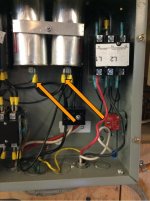
So I pulled those wo wires and started the RPC.
Got some noise and white smoke on the left side.
Hit the breaker.

Something blew. Put the wired back and tried again, but it won't start.

If I take an amature guess, did the blacks on the left blow due to insufficient capacity?

Here's a full,pic
image.jpg
 

Attachments

  • image.jpg
    image.jpg
    18.6 KB · Views: 247


Back
Top