I have a Sebastian lathe with what I originally thought was a three phase motor. After cleaning the wiring up I believe it is a single phase dual voltage motor. I have six leads, three yellow, three black. There are three pairs I was able to identify using an ohmmeter (no labels or tags on the wires). The yellow of one pair is connected to a capacitor. I am assuming I have two run circuits and one starting circuit.
I am assuming this is single phase. The only other explanation I could come up with is that this is a six wire three phase with a starting cap on one phase to get it to turn over and run on single phase. (simple static converter type setup). I don't believe this is the case but it is a possibility.
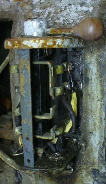
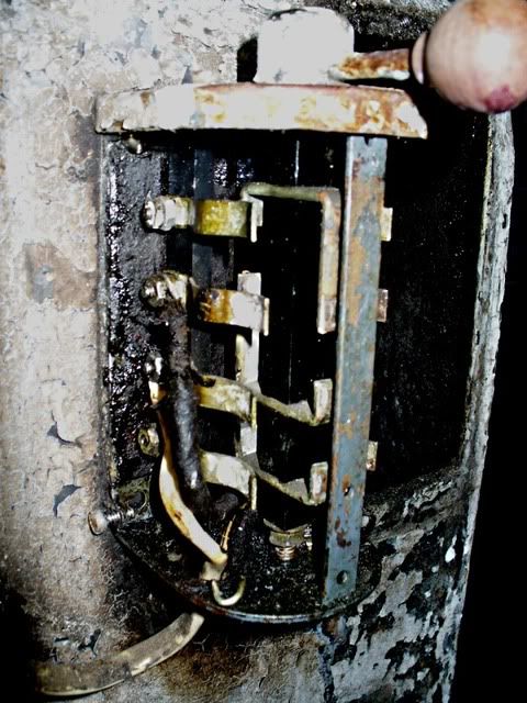
Here are pictures of the drum switch. Please pardon the Romex. I'm trying to clean up after the previous owner's wiring job.
I have two ideas about how to wire this motor and the switch. One requires seven of the contacts to be used (and five wires between the switch and motor not including L1 and L2(my two hot feeds)) and the other method involves just five contacts and three wires not including L1 and L2. I feel a bit more confident about the first method actually working, but I am wondering if the second method would work just as well. The first method is based on the diagram labeled "dual voltage main winding only":
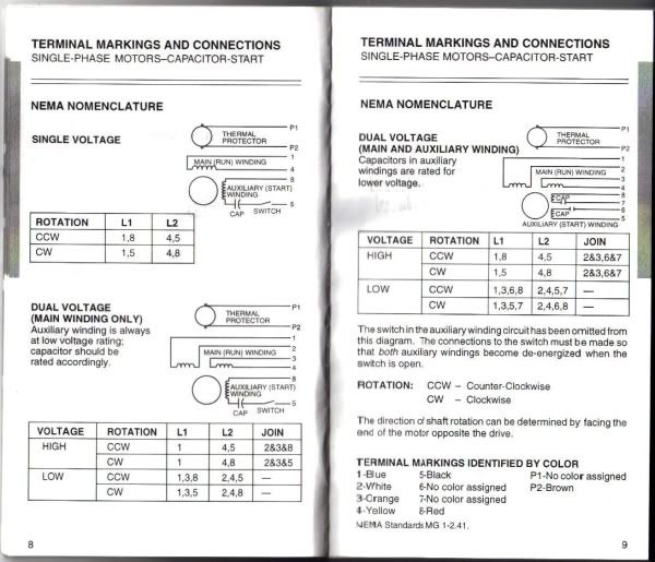
The second method comes from diagram 1 on the top left (higher voltage):

I'm using the following numbering scheme:
1: First run circuit yellow
2: First run circuit black
3: Second run circuit yellow
4: Second run circuit black
5: Start circuit yellow
8: Start circuit black
Since I will be running this motor at 220v I am assuming I will need to connect the two run circuits in series. This means #2 and #3 will be tied together. The following diagrams should be now be understandable.
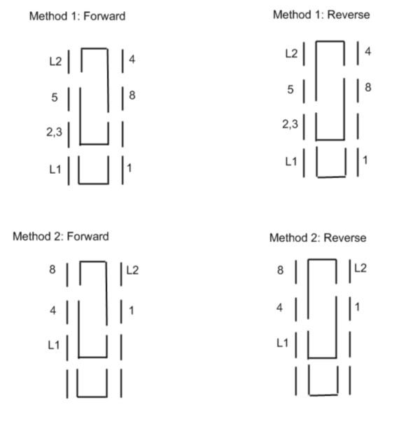
Are both methods correct? Will Method 1 work properly? I would like to use the simplest connection method.
EDIT: I see my ASCII diagrams don't display properly when posted. I will draw them up and post them as photos in a few minutes.
I am assuming this is single phase. The only other explanation I could come up with is that this is a six wire three phase with a starting cap on one phase to get it to turn over and run on single phase. (simple static converter type setup). I don't believe this is the case but it is a possibility.
Here are pictures of the drum switch. Please pardon the Romex. I'm trying to clean up after the previous owner's wiring job.
I have two ideas about how to wire this motor and the switch. One requires seven of the contacts to be used (and five wires between the switch and motor not including L1 and L2(my two hot feeds)) and the other method involves just five contacts and three wires not including L1 and L2. I feel a bit more confident about the first method actually working, but I am wondering if the second method would work just as well. The first method is based on the diagram labeled "dual voltage main winding only":
The second method comes from diagram 1 on the top left (higher voltage):
I'm using the following numbering scheme:
1: First run circuit yellow
2: First run circuit black
3: Second run circuit yellow
4: Second run circuit black
5: Start circuit yellow
8: Start circuit black
Since I will be running this motor at 220v I am assuming I will need to connect the two run circuits in series. This means #2 and #3 will be tied together. The following diagrams should be now be understandable.
Are both methods correct? Will Method 1 work properly? I would like to use the simplest connection method.
EDIT: I see my ASCII diagrams don't display properly when posted. I will draw them up and post them as photos in a few minutes.
