Couple observations:
It looks like the readings you quoted are line to ground, since you didn't specify what 2 legs you were measuring from.
Since the drawing shows no part of the output winding is grounded, the voltages to ground are meaningless. They are just capacitatively coupled voltages.
How balanced are the input voltages? If the supply is a center tapped delta with a wild leg (RPC), one would expect the voltage to ground to be unsymmetrical, even a capacitavely coupled one.
Looking at the drawing, it appears that more jumpers are needed than what is shown on the voltage selection chart.
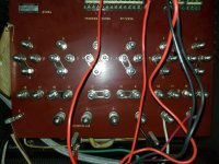
Drawing shows a delta connected input, with a jumper between phases, that is not shown in the photos.
#12 of phase A to #4 of phase B, similar for the other phases
Also missing is other interphase jumpers, as I read it.
Phase A should have 9,4,1,10,8,5 and #12 of phase C connected together. For one side of the input to phase A.
The other input side of phase A should be 11,12 and #4 of phase B
I don't see all of those connection in the photos provided, but you don't show the thing in its entirety, the input lines are not shown. There could possibly be other jumpers not shown, but it doesn't appear so.
I don't have time at the moment to make a drawing, but the missing links are shown on the drawing you posted along with the jumper link connection chart.
SAF Ω