What's new
What's new

Vfd control wiring

Cadillac

Aluminum
Joined
Mar 12, 2016
I have a 13x40 optimum lathe. Im in the process of wiring in a vfd. One problem I've run across is getting the oprators green "run" light on the face of the machine to work with control circuit for vfd. The light is used to tell operator all safety's are correct and ready to spin.
The problem I've found is how to wire the light so it's functional? The vfd states not to use vfd 12v source to power external devices. I've been trying to think of a way but can't.
Another thing was the manual shows a couple wiring configurations. Two or three wire control circuit. They show using a two position rotary switch for forward and reverse control. My machine has two micro switches opposing each other on the apron for forward and reverse. I really want to keep this configuration just rewire switches. Should I be worried about anything using my existing switches with rf frequencies or anything like that. Read so much conflicting stuff the more I read seems the more confused I get. :confused:
 
Can you just switch the light off a SSR wired to the VFD? I haven't looked at the specs lately but I can't imagine one drawing any meaningful amount of power.
 
Unfortunately I only know enough about electrical to be dangerous:( Can you explain? Im willing to learn.
 
Solid state relay is basically a circuit which does with transistors what a normal (electro-mechanical) relay does with coils as electromagnets.
 
The forward/reverse switches on the apron should be no problem. If you are worried about RF then use shielded motor wire. On a lathe like yours the VFD is usually mounted on the rear, so the motor wire length will not be long.

I wouldn't make a guess about your apron green light. Does it stay on 100% of the time? Or does it go out when the lathe starts turning. In the field green means stopped and ready to run, red indicates machine is running. If you are willing to do a little re-wiring for the apron a red/green high output led would be a good way to go. If the green light is really a light bulb behind a green plastic lens then you have to make a few changes with a clear lens and a led socket. I can think of at least half a dozen ways to do this with the parts I have on hand.

With regard to three wire control, a red and green light is usually used. Whether you can do that with your VFD input/output terminal block I don't know. A little knowledge about your VFD is in order to get more specific answers.
 
After looking at the schematics for the original wiring of the lathe the light comes on when the main power switch is thrown.
I purchased the lathe and tore the electrics apart to wire in the vfd. My garage doesn't have 3 phase so this needs to get done to operate.
I ran the machine prior to purchase but couldn't remember how the light operated.
I have the power side all wired now working on the control side. I have shielded wire for controls. I have maintained micro switches on the for/rev lever on the carriage. It shows in the PDF manual in their 3 wire schematic using momentary. When sending these signals are they momentary or maintained? I have a teco L510-202-h1-4 it's a 2hp model. I really would like to keep e-stop button,jog button on face of lathe. For/rev micros on carriage and a second e-stop with foot brake. The manuals only show basic run stop methods.
I do have a 24v transformer that was in the original lathe wiring along with contacters. I also have 120 v contacters. Just don't know how to wire them if they'd work.
Any help would be appreciated thanks!
 
The light on my 13x40 is powered by the 24v transformer. I wired it in series with the safety interlocks (gear housing, chuck shield, and e-stop), and then converted the jog button to a "power-on" button. The button engages a contactor that completes the circuits used by the apron switch to run the lathe in forward or reverse. If any safety interlock is open (cover off, chuck shield up, or e-stop pushed), it breaks the circuit powering the contactor and stops the lathe. My VFD has an integral NEMA-4 enclosure and a jog button on the face, so I mounted it above the spindle end of the lathe and use the potentiometer for speed control (in addition to the gear box) and the jog button (@ 5Hz - programmable) when I want that. If your VFD is mounted inside an enclosure, it sounds like that won't work for you since you would lose your jog button. I couldn't find a way to connect a remote momentary switch to my VFD for the jog function.
 
They show a in the online manual a way to wire two jog buttons. One rev, one forward. I don't wanna add another jog button.
What's the reason for jog button other than meshing gear train when switching gears? I don't plan on switching gears to often hence the vfd. Right?
Wouldn't power on happen when I throw the main switch on my original enclosure which would power up the vfd and Im planning to have illuminate the green light on the face of the lathe.
Are your apron switches industrial micro switches with three terminals and maintained switches?
Well I'm definitely learning specifics through this process.
 
My apron switches are whatever was installed in the lathe from the factory. I haven't had that part of it apart (yet). I metered the existing wiring to see which of the four wires did what. There are two separate switches, and they are maintained contact.

For me, a jog button can be used to rotate the work when the lathe is geared down to a slow speed and the chuck is difficult to turn by hand. I DO use the gearbox to get into different speed ranges, and then fine-tune with the VFD. At some point, I plan to install a digital tach on the lathe somewhere, as I don't think the VFD has the capability to know the spindle speed without a separate sensor, and I don't know if that is possible, either.

The power light on my lathe was powered by 24v as wired from the factory. I don't know how I would have powered it through the VFD, and the way I have it now it is a visual reminder of whether the lathe is in a run-ready state or not. My 24v transformer is powered up when the lathe is plugged in, regardless of whether the VFD is switched on or not. There's probably another way to do that, but I don't know what it is.
 
Im getting ready to do the same thing to a bigger enco lathe. Its a 5hp 1440. I have an American Rotary phase converter but the lathe doesnt run well on it. Im going to use a VFD from Automation direct. 3ph in, 3ph out. Have you gotten any of the wiring done yet?
 
Im getting ready to do the same thing to a bigger enco lathe. Its a 5hp 1440. I have an American Rotary phase converter but the lathe doesnt run well on it. Im going to use a VFD from Automation direct. 3ph in, 3ph out. Have you gotten any of the wiring done yet?

If this is directed at me, then yes. I used a KBDA-27 VFD from KB Electronics, partly because it is already housed in a NEMA 4X enclosure.

It works pretty well, though not quite as I expected, and I'm still wondering if I did something wrong. When wiring the controls, I thought I had an option to wire the existing apron switch as "Forward Run/Stop" and "Reverse Run/Stop" using two inputs in the IODA add-on board, but I actually had to use three of the inputs and put a diode between "Run" and "Forward" and a diode facing the other way between "Run" and "Reverse". It works great, but I don't know if it is correct. I intend to call KB Electronics about it at some point, but you know how it goes. It's working, so it hasn't been a priority.

I didn't wire up a remote pot since I attached the box to the top of the lathe where I could reach the control pad and built-in pot.

{Edited for better accuracy/clarity}
 
Last edited:
As for mine I'm 75% there. I'm using the existing enclosure on the back of my lathe and retrofitting everything. Originally it used 24v for controls,machine light,etc. I switched over the machine work light to led 12v.
Added cooling fan which operates off 120v.
Added a digital rpm display on operator panel along with pot dial for frequency adjustment. Cutting and drilling through 3/8 cast sucked :ack2:but finished product looks factory.
Made bracket for prox. Sensor to read spindle.
Wiring for pot dial is straight forward one way.
Power side to vfd a output to motor are also straight forward.
Control side of wiring is probably the same but for some reason I'm having difficulty understanding some parameters. I want to use all the original controls I can.
Jog button on operator panel
E stop on operator panel
Forward/stop/reverse on apron lever
E stop on foot brake
Now I've ran all the shielded wire to the locations on the lathe. Wired what I'm confident in. And figuring out what I can. It's just any info I find isn't very clear or I'm just not picking it up. And the worry of smoking something out.
Right now I'm working on the switches. I believe all the switches should be maintained except the jog. But in my vfd manual it shows momentary. They are also using a three position switch for for/rev. Where I wanna use the existing micro switches on the apron lever. So I'm at a stand still till I can figure it out. Luckily I have a second lathe to get my projects done till the new one is up and running:toetap:
So close but yet so far :ill:
 
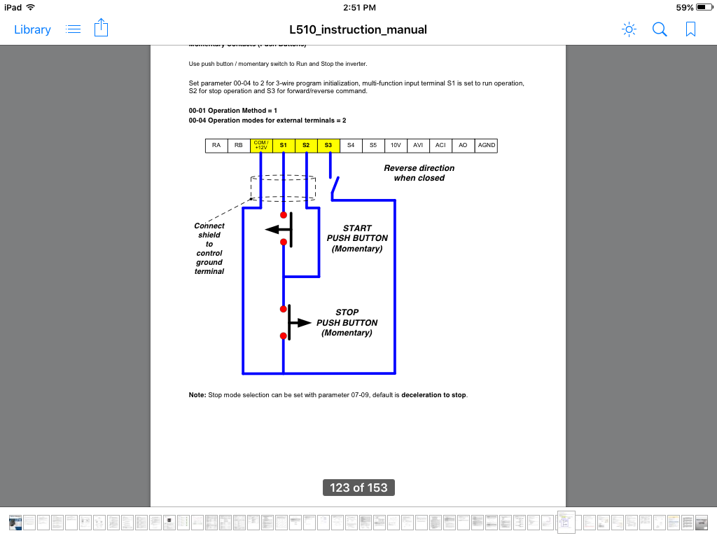
Here's one of the diagrams in the manual. Which i think is not drawn correctly.
How is s1 gonna get power unless the stop button is activated,which in return would send power to s1 switch but in process send power to s2 terminal which is stop. Am I wrong by thinking you can only send power to one terminal at a time? Do these switches need to be maintained for power to terminals or just sending a signal to activate?
Lastly I need to run the com/12v terminal to five different terminals. Is the correct way to run a wire to a terminal block then branch off that. Would think that takes away from "shielding"? Any help would be appreciated thanks.
 
I've worked with a lot of drives over the years most can be wired 2 wire control or 3 wire that's what your showing it will have to be programmed for that ,most are default 2 wire i.e. Common + run forward or common + run reverse
The diagram is correct
You could connect the common directly to the start button that would allow you to hold the stop and start buttons in and jog by releasing the stop button ( only 1 operation instead of start and stop)


Sent from my iPad using Tapatalk
 
If you don't want to have a start and stop button just leave it set up for 2 wire you can have a maintained switch for each direction that can be your jog if you leave the accel time set high it will start slow anyway


Sent from my iPad using Tapatalk
 
What I have found after retrofitting many of vfd's on machines is to simply pull off and wire nut "A Phase" on both forward and reversing contactors and use that pole of the starter to control vfd simple and all the machines original functions still work
Also we need to remove motor leads from these contactors and take directly to VFD
Good luck


Back
Top