What's new
What's new

VFD or DC drive for Universal Motor?

Colt45

Hot Rolled
Joined
Nov 27, 2004
Location
SLC, UT
Need a drive to control a "Universal" motor in a lathe I am rebuilding (feed motor, drives a reduction gearbox).
Would like the motor to have variable speed (will use outboard potentiometer to control the drive) and excellent regulation of speed.
Assuming the price is the same, is there any reason to prefer a VFD vs a DC drive for a universal motor?

May not even need a DC drive - unless you need tight regulation under varying load. That isn't really a Series/Universal wound motor's best use, but it can work. Series-wound can deliver a lot of power, but run "naked" they expect to be allowed to speed-up or slow down to match the load. Shunt-wound OTOH, try hard to self-regulate.

Variac's work fine for my "Precise" grinders. Not much change to their load once the wheel is in contact.

"Classical" VFD aren't an option, ordinarily. Single-phase motor, even if AC/DC-friendly.

There are some newer approaches finding their way into cordless power tools. No idea how suitable those might be for your application, torque & RPM-wise. Our PM meber Mattij in Finland may be able to assist. I'm not current, nor expect to be.

I think the greatest barrier is that they are engineered as a complete "system' and may be difficult to re-purpose as severed components for onesies or fewsies.

Another option is a fractional HP DC gearmotor. Some are around as reasonably priced NOS, not ever used. I have a Bison I've tested and set aside for the tiny Burke #4 mill. Bodine, I've always liked even better.

As to "excellent regulation"? See the percentage figures on DC drive pubs. Inherent Armature feedback, onboard reference source, biased op amp for comparator, and it ain't half bad. Add an Analog tacho, and the CLAIMS at least are seriously better.

These want an old-school analog tachogenerator, not because resolvers aren't generally better, if not also cheaper, long-term, but because nearly all the economical DC Drives have inputs to utilize Analog tacho, but few have inputs for Digital.

Not really a "cheat" but for the most part, they just jumper or switch the lead that WAS tapping the Armature output off to a terminal for the Tacho input, set other switches or jumpers to a resistive array that selects the Volts per 1,000 RPM expected. Not lot of extra parts involved to make analog tacho control possible, IOW.

For a digital pulse stream there are cheap IC's for conversion, frequency from the pulse train to Voltage level ramped - I have several type around.

OTOH, it's a R-PITA to build, calibrate, keep in calibration, when a ServoTek tachogenerator is only about $25-$120 used, and probably $300, new -depending on space available and mounting options.

Small size?

You can probably find very affordable servo motors and kit to operate them.

I'd go there rather than mess with a universal wound motor on any sort of lathe traverse drive system. MUCH easier to nail the stability issue reliably.

Otherwise? The Series type motor is not always supported by inexpensive DC Drives anyway. Shunt wound essentially always is, PM or wound field, brushless or brushed.
 
Series motos are nominally AC/DC, but most are best in AC. All you really need is a router motor control box. NO NEED for a VFD, nor would it even work very well.

If you need speed accurately controlled, then you need feedback and a control system. They do exist. But probably you do not need it as much as you think.

How is this existing feed system controlled as it was designed?
 
The motor is in a Monarch 10EE "manufacturing" lathe, though I did not get any of the drive components and all the controls were gone.
Most of the manufacturing 10EE I have seen have a simplified version of the threading gearbox, driven by the spindle. This machine did not--it has the universal motor connected to a single speed reduction gearbox connected to the feed rod. No real idea how the motor was controlled, except there are wires that run from a tachometer on the spindle to the Universal motor.

I don't know for sure, but several features of the machine suggest it was originally configured for production of a specific item.

I considered just finding a clean used servo motor with encoder and direct drive the feed rod instead of using the factory universal motor and reduction gearbox-am open to suggestions .
 
I considered just finding a clean used servo motor with encoder and direct drive the feed rod instead of using the factory universal motor and reduction gearbox-am open to suggestions .

Since you have to do "a lot", regardless of the path taken, I'd go for maximizing the return on all that cost and effort.

My vote would be to go directly to full-featured "Electronic Leadscew" servo capability instead of using the universal motor at all.

On-Edit & reflection: I'm not so sure I'd even equip for threading at all.

With the ready availability of all manner of store-ought / online-ordered threaded goods, plus taps and dies, plus - I'm guessing - one or more OTHER lathes already able to siogle-point?

Might be more than good enough to provide only a good power surfacing drive capability, this one lathe.
 
Last edited:
The best speed control for the money would be to separate the armature and field and supply the field with a regulated voltage which will be some portion of the line voltage, then vary the armature voltage to control speed.

I think you need a closer look at your motor. A simple series wound one would be a poor choice for the application and unlike Monarch. I would be very surprised to find that it did not also have a shunt field as well. Guessing at the problem without knowing more about the motor is just guessing.

Is the motor reversed in normal use?

Bill
 
I think direction reversal is done via the gears in the apron.
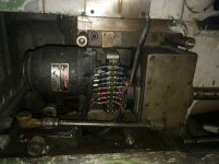
Motor is made by Lamb Electric- Specs are 1/8hp, 115 volts, 4.5amps and 7900rpm.
The gearbox between the feed motor and feed rod is a 14:1 reduction.

Machine was built sometime in the 1960s. I find it interesting how things were done before modern digital controls, VFDs, servos etc.
What would be the design philosophy behind such high rpm on the motor and using a gearbox, vs just using a bigger motor and direct driving the feed rod?

IMG_2761.jpg
 
I think reversal is done via the apron.
Motor is made by Lamb Electric- Specs are 1/8hp, 115 volts, 4.5amps and 7900rpm.
The gearbox between the feed motor and feed rod is a 14:1 reduction.

Machine was built sometime in the 1960s. I find it interesting how things were done before modern digital controls, VFDs, servos etc.
What would be the design philosophy behind such high rpm on the motor and using a gearbox, vs just using a bigger motor and direct driving the feed rod?

View attachment 226430

Weird. Lamb? Those folks once dominated vacuum cleaner motors, household on-up.

No matter WHAT you had, if it sucked dirty air or pushed it around - there was a Lamb drop-in motor for it.

I once owned 980 lbs of 130-column 1000 line-per minute Data Printer 1064LP. Built-in? 5 HP Lamb vacuum system and plumbing to the pin-tractors- just to keep chaff and paper dust under control as it slewed 21" superfold paper.

Lamb was everywhere. Nearly always out-of-sight, though.

Screaming meemie surely seems a mis-match for a machine-tool, geared or otherwise.
 
Sounds like you would be better off with a single capacitor type gear motor, and a small single phase VFD to operate it. That would be pretty stable.

Some cobble-up DC deal could also work, but I suspect it will be easier to take a different approach.

The series motor is not too sensitive to frequency, so a VFD is overkill for it. The main effect is likely to be the voltage variation that goes with it on a VFD.


Back
Top