What's new
What's new

VFD and Momentary Push button Relay wiring

auswelder

Plastic
Joined
May 5, 2018
Hi all,

I have a VFD that I am trying to setup on a lathe with momentary push buttons for Start, Stop and Jog and a selector Switch for Forward/Reverse. In the manual I found a wiring diagram but am not sure what type of relay to use, and were to attach the switch to appropriate terminals of relay/vfd. I believe the relays are normally numbered.

Any help would be good.

Thanks

vfdrelay.jpg
 
Maybe you are right there, the relay could be internal? Did you have a look at the diagram?

Thanks
 
Hi all,

I have a VFD that I am trying to setup on a lathe with momentary push buttons for Start, Stop and Jog and a selector Switch for Forward/Reverse. In the manual I found a wiring diagram but am not sure what type of relay to use, and were to attach the switch to appropriate terminals of relay/vfd. I believe the relays are normally numbered.

Relay MAY be already on the PCB. Giving it a "number" is the klew. See the physical layout section of the manual. If so, size of a (small) ice-cube. It is cheaper for the maker to include one on every PCB, even if never used, than to deal with the service calls about either confusion or damaged VFD.

If No Joy, you "tecnnically" need a 3PST. Three poles, single "throw", 24 V operating coil.
The + sign on the schematic indicates that should be a DC coil rating. Most times, AC or DC coil doesn't matter in these small units, so they may be listed AS "AC/DC".

It will usually be better, easier and probably cheaper, to use the "appropriate" side of a 3PDT or a 4PDT (double throw) for future flexibility.

Cheap enough stuff, and all over the place. The simplest of many players as to "contact form", if that should confuse your search, is explained here:

Understanding Switch Topologies - National Instruments

..but doesn't much matter in this application. It ain't the "hook switch" for a 1960's 4W E&M multi-line telephone set.

:)

Look for a built-on first, as you need a place to PUT the thing SAFELY and fasten it as well as wire to it if you have to furnish your own. Adhesives can work for that. The fastening. Not the wire.
 
My take on the instructions is the relay is user-added modification. You would need a 24 volt dc coil relay that has
at least three normally open contacts. (probably 3PDT would be the least expensive one to get)

The page you provided does not show the fwd/rev connections, those will be in another section of the manual, and
probably will require a SPDT toggle switch.
 
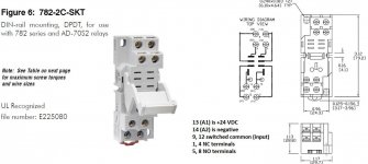
The wiring shown is 3 wire control, terminal 11 sets the direction with open is forward and closed is reverse. I do not see the purpose of the relay, and it would be a DPDT (relay 1 NO x 2) since only terminals 10 and 13 are switched. It would also appear that as shown the relay is powered by the VFD (terminals 4 is negative and terminal 14 is positive 24VDC). If you went the relay route you could use something like an Automation Direct socket 782-2C-SKT, relay 782-2C-24D, AD-BSMD-250, the terminal wiring is per the instructions (see below). The JOG would be a single pole momentary switch. Alternatively, use a momentary button switch with two NO contacts and achieve the same results with no relay. The inputs are both connected to terminal 7, the output of one block to terminal 10 and the other switch block to terminal 13. I often use a 2 way JOG joystick and one can control both JOG and direction at the same time. It would be helpful to know the VFD model/brand so the rest of the manual could be reviewed.
2P relay.jpg
 
What makes it confusing is that the Forward/Reverse switch is drawn right inside the relay "dotted line", but it is a separate switch and has nothing to do with the relay.
 
I can tell by the parameter numbers and the save sequence that you are working with a Control Techniques Drive . . . Which model number are you working with?

mksj has the right approach, you can just use a double contact push button for the JOG function and skip the relay altogether.
 
The prior example in the manual shows it more clearly, so taken in sequence,the first example is JOG without F/R and the second with. I would go with a dual pole jog switch and just omit the relay. Typically I do not use 3 wire on lathes, I go with 2 wire with interlocked relay controls, direction is either with via a spindle direction switch or using separate momentary for-stop-rev buttons.
Manual for Commander SE https://www.google.com/url?sa=t&rct...EAUGiss3.pdf&usg=AOvVaw1MtRXdE6jc3NSWcJ40m9Ta
Jog Command.jpg
 
Yes it is a Control Techniques Commander SE 1.5M 0.75kw. I think the relay is already on the PCB as I can see something there.

The way I was hoping to have it set up is as the following.

Start: momentary push button
Stop: momentary push button
Jog: momentary push button
Direction: 2 Position Selector Switch
Emergency: Esop style switch

The swiches I have are configurable for either normally open or normally closed.

So going by this then it should work without the need of any additional relay?
 
The relay is ONLY for invoking the JOG mode IMHO. If you don't think you'll ever use JOG just wire the run and not run momentaries and your fwd/rev switch. If you need JOG then add the 24v coil and wire as per diagram.
 
The only relay shown in the manual is a single pole (terminals 15, 16) configurable to monitor VFD functions/actions. So you would need a stand alone DPDT relay if wired per Section 12.22, as it does not show the JOG (example 2) wired to the VFD relay. My take on the use of the JOG DPDT relay is so one can use a SPST momentary switch for the JOG. This simplifies the wiring, otherwise use a dual pole momentary switch and omit the relay. The switches would be configured per Example 2, and the VFD programmed accordingly.
 
Anyone know this particular drive. I am having trouble accessing the Parameter setup menus to configure these switches. If I go to option 10 on the Menu I can configure it to access L1, L2 and LOC menus which give additional parameters but can't seem to access 6.04, 8.22, 8.23 etc
 
Most VFDs have some form of parameter lock feature, and the default usually limits the parameters that can be edited. On this particular VFD model see parameter 25, 11.44 (security Status) of the manual, it would need to be set to "1" instead of "0" to access all parameters.
 
Playing with that 25 setting basically put a security code on the drive, now I can't change most of the settings without it asking for CODE. Is there anyway to revert back to factory settings without knowing this code? Even going to Setting 29 (factory defaults) is asking for the code. argh


Back
Top