What's new
What's new

Vintage 3-Phase Motor Rebuild

Clownshoes

Aluminum
Joined
Apr 22, 2009
Location
NC, USA
20170619_101756.jpg20171202_165428.jpg
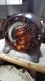
Background: Near the end of a lathe rebuild project I had been working on I had to make a decision about what to do with the motor it came with. It worked when I got it but like everything else was not in any kind of condition to be used with any type of confidence. The motor appeared contemporary to the lathe (though I'm fairly sure it is not the original) so my natural inclination was to reuse it but I was not certain what that would entail. I contacted some local businesses to see about having it done professionally and no one would quote me a price without seeing it in person but I was not keen on lugging a dirty 100Lb motor around town simply for an estimate. I started researching online what it took to rewind a 3-phase motor and had quite a bit of trouble finding any information in english. The majority of information was coming from indian or thai sources who seem to have a lot more interest in motors than we do in the states. Of the information I was able to find none were identical to the motor at hand but I began to piece together the general process. I contemplated purchasing a new motor but could not get over the poor aesthetics of them and was dismayed to learn that vintage motors in good condition aren't readily available since a number have gone the way of the scrap yard for the copper inside. Once I felt confident I knew what I was getting into I decided to go at it on my own and I wanted to share the process I went through in hopes of saving more vintage motors from the scrap pile. I want to mention I am a mechanical engineer, not electrical, so I can't say much about how the motor actually works (oddly enough my EE friends couldn't either) I just know what the guts are and how it all goes together.

Step 1: Motor Specs
Easy stuff - 3 phase, 3 HP, 220/440V, 60Hz
Not so easy stuff - 16 AWG windings, 24 turns/coil, 36 coils, 12 coil groups, double layer winding.
The double layer winding was important as all the videos I had seen were of single layer wound stators, this I had to completely figure out from the original windings and made very little sense at first but once I got it, it was pretty straight forward. Basically every stator slot is occupied by two sides from different coil groups.
20170924_221621_1.jpg
In order to begin I peeled back the wrapping and cut one coil on the non-terminal end of the stator. If you can do this with one single cut it helps deducing the amount of wire needed later on. Everything will be caked in varnish and if it's old like mine it crumbles apart pretty easily. From here you can determine the gauge of wire and number of turns and this last part was somewhat confusing. The number of wires you count here ends up being N+1, where N is the number of turns/coil. This didn't make sense until I started winding small samples of wire as a mock-up and I can't really explain it any further than that. At this point I still have no idea how many coil groups I have or how many coils per groups there are or what direction everything is wound.

Step 2: Terminal Connections
Flipping the motor around to the terminal side, I placed a piece of masking tape around the inside of the stator and numbered each slot. I labeled the slot where T1 exited as slot "1" and went from there, this is for reference only but was very helpful in figuring out the winding pattern. Here I recorded every slot that had a terminal exiting from it and where it went, whether it was an internal connection or one of the nine terminals that exit the motor. Here you can also confirm your coil span which is very important, in this case it was "7" which means if you counted over 7 slots from the side of any one coil you would find the other side and since it is double layer it would be opposite the slot position of where you started (top or bottom).
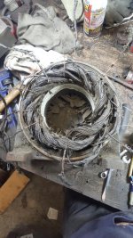
20170926_022723_1.jpg

Step 3: Wiring Diagram
Once all the terminal and slot location information was recorded it was time to create a diagram. If you look online most everyone will write out the slot numbers in a linear fashion and draw in the coils as a diamond or some other shape but I found this very confusing and could not keep track of where everything was being connected so I drew my own similar to what I was actually seeing. At first I only had the terminal location information and was not certain how all the loops connected or interacted with one another but once I had it drawn out and started looking closely at the standard "Y" diagram for 3-phase motors, things began making sense and I was able to determine that I had 12 coil groups with 3 coils/group, and playing around with some mockups I determined everything was wound clockwise in order to lay down properly in the slots.
20170929_014002.jpg
 
Somewhere in my house I have some old electrical books (Audels?) that explain in detail how to rewind motors. I can dig them up for you if you want. They came from the thrift shop I volunteer at, so they didn't cost me anything. I have no use for them but they might be useful after the apocalypse.
 
Step 4: Removal and Cleaning
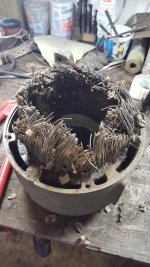
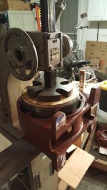
Satisfied all the important information needed to to rewind the motor was recorded accurately it was time to remove the old material and begin cleaning everything in preparation for the rebuild. I stamped my slot "1" for reference and to remove the old coils I cut them all at the non-terminal end and pried them out the other end using a steel rod and dead-blow hammer. If you watch videos of the indian or thai guys they will often pour kerosene on the whole lot and set it on fire to burn off the varnish first, this seemed like a bad idea so I skipped this step. As the coils were being removed there was concern about delaminating the ends of the stator as they were being bent in the process, I damaged a few and broke one trying to bend them back but in the end it was all unnecessary as they get held in place nicely by the new coils and insulation paper but we'll get to that later. After all the old coils were out, I removed two set screws in the bottom of the stator housing and pressed out the stator using an arbor press.
20170930_153411_1.jpg20170930_222916_1.jpg

I used two methods to calculate the amount of wire needed to rewind the stator, one was a before and after weight of core with and without the copper, the other was to measure single pieces of the removed wire which if only a single cut was made through the loop should represent the length of a single coil turn that can be multiplied by the previously obtained values to get a bulk length. Both measurements correlated fairly well so I went ahead and started ordering material at this point. I was also able to get a close look at the slot wedges and insulation paper which needed to be ordered as well. Material selection could be it's own thread so I won't go too much into it here but will be more than happy to answer any questions.

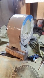
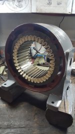
Once apart, the stator and housing were stripped and cleaned. The stator got few coats of insulating varnish and the housing was primed before being pressed back together. Once back together the housing was top coated.
20171008_174042_1.jpg20171008_185942_1.jpg20171008_200852_1.jpg
 
Last edited:
Step 5: Slot Insulation and Coil Winding
Prior to receiving the new coils, each slot needed to be fitted with a piece of insulation paper. This protects the coils from grounding to the stator. Each piece has the ends folded over before it is bent into a "U" shape in order to keep them in place and provide extra protection around the sharp edges at the ends of the stator. To do this a small forming tool was milled out of aluminum that could consistently and easily shape each piece since it needed to be repeated 36 times.
20171014_175923_1.jpg

Now came time to wind the coils. This was done using a simple piece of plywood with nails. Each coil was zip tied to keep them separate. This part was not easy on the hands and I recommend using a good quality leather work glove that allows the wire to slide easily through it while still keeping tension. Once I had three finished coils I released the tension by removing one of the smaller bits of plywood in the middle and sliding the coils off the nails. This is probably a good time to mention that while the mag wire is technically insulated with an enamel coating, it comes off readily if scraped against anything harder than wood or plastic, from this point on take care to avoid damaging the coating. Some marring is acceptable as everything will be soaked in varnish in the end but there aren't any easy methods of determining an in-coil short so doing your best to not disturb the coating will give you piece of mind later on.
20171014_225937_1.jpg20171015_152446_1.jpg

Step 6: Inserting Coils
After all the coils are formed they can begin going back into the stator. Again you want to avoid any damage to the coating and the sharp edges of the slots will do just that so use pieces of insulation paper or something similar as a guide to keep them from coming into contact with the stator during insertion. Also there will be a need to push the wires into place at certain times, do not use anything metal for this, I recommend the thin wooden sticks you can get at craft places. Once installed the coils can be held in place using slot wedges. Since this is a double layer wind it is necessary to populate the bottom of several slots before the coils can be laid over and inserted into the top of the slots, everything kind of gets buried under adjacent coils as you can see. I will note my first go at this was a total failure, Initially I used the same thickness insulation as the original but it ended up leaving insufficient room in the slot for the two coil sides and two slot wedges. I damaged my first four coil groups before deciding I needed to order a thinner insulation paper. After the new paper arrived and new coils were made to replace the damaged ones everything went much smoother and I was able to work my way around the stator populating each slot. In regards to the slot wedges, these were really the only speciality item that proved somewhat hard to find and I had to buy way too much but it was good I did as several had to be discarded when they became too bent up to go in. Their purpose is to insulate the two sides in the slot from one another (which are different phases) and hold everything tightly inside so the wires can't spill into the rotor area. They should be tight to get in and I found it worked best to install the outer wedge first then shove the middle one in last.
20171028_155952_1.jpg20171030_025544_1.jpg
 
Last edited:
Step 7: Forming Coil Ends and Phase Insulation
Once all the coils are secured in their slots, the ends need to be formed to ensure they are not encroaching into the rotor area. To do this a soft-faced rubber mallet was used and the ends were beat into place until they began to resemble the original windings and the rotor could be freely inserted without touching any of the windings. Also be sure the end bells can go back on without contacting the windings. After being satisfied with the shape it is time to install the phase insulation, again the idea here is to prevent any arcing between the three phases. Use the wiring diagram to identify the boundaries between the phases (which is the same as the boundary between coil groups) and insert a piece of insulation paper accordingly. I saw some people who insulated between every coil and some who just insulated between phases, I opted for the later as it was how the original was done and it seemed overkill to do each coil. Since at this point the non-terminal end needed no further work, it was soaked with a few good coats of varnish and the wrap applied. Make sure the wrap is tight, the goal is to create as close to a solid mass as you can. Anything loose may vibrate and wear over time generating arcs between windings which will eventually lead to motor failure.
20171104_195026_1.jpg20171104_214033_1.jpg

Step 8: Terminating Coils
After inserting the phase insulation on the terminal side similar to the previous step, the coil ends can be terminated. Each coil group has a start and a finish and all need be terminated based on the information from the wiring diagram. In general you will terminate start to start and finish to finish. The nine terminals that exit the motor will need leads attached that can be terminated based on preference, I chose ring terminals. Every coil end is labeled based on it's location on the wiring diagram and coil group and whether it is a start or finish. If all the coils were installed correctly all the starts will occupy the same slot position (top or bottom) and like wise the finishes will be in the other position. It is important to not lose track of any terminals at this point. I purchased two types of sleeving for the terminals and both ended up being garbage so I went with all heat shrink. For the nine terminal leads I used lengths of 10 AWG machine wire. After all the connections were soldered and heat shrink in place, the nine terminals were routed out of the housing similar to how it was done originally. This is where marking my original slot "1" proved useful as it allowed me to replicate how the terminals were routed without any guesswork. Varnish was once again applied liberally to the coil ends and the wrap applied. Further coats of varnish were applied to the wrappings at both ends to help secure everything in place. Now that everything was wired, continuity checks were performed on all nine terminals to verify the connections and make sure nothing was grounded to the motor housing. To somewhat reassure myself that there were no significant in-coil shorts, I calculated the resistance per coil and checked each one with a multimeter. Each coil had under an ohm of resistance which can't really be reliably measured with standard equipment however once all connected you end up with two or more coils strung together which amount to greater than one ohm so while still difficult to measure accurately without expensive equipment it gave me some consistent results that were close to the calculated value.
20171104_222341.jpg20171105_225658_1.jpg20171106_005813_1.jpg
 
Last edited:
Step 9: Rotor Cleanup and Final Assembly
The rotor was cleaned in similar fashion to the stator, the core was hit with a coat of varnish and the aluminum bits were coated with some silver paint just to prevent future corrosion. The end bells were reassembled with new SKF bearings. New tubing was made for the grease ports and fitted with zerks. The motor was assembled in place on the platform of the machine to avoid having to heft the full weight of it into position. All the external connections were made and after some time remembering how to program an inverter the motor spun up readily and in the proper direction which is always nice. The RPM was checked with a strobe and was found to be dead nuts at 1800.
20171121_124232.jpg20171107_215928_1.jpg20171202_165409_1.jpg20171202_233442.jpg

Overall I'm happy with the outcome and glad I opted for the rebuild. It has yet to really be put to work but so far no issues that I can tell. I really enjoy how the motor looks and I like knowing what all the internals are and how they were sourced, something I might not have if I had sent it out to be done. Not sure if I'd ever want to do another one, the worst part was inserting the coils and wrestling with the slot wedges, each coil group took a good hour to get fully seated and my fingertips were in bad shape for weeks after. Some parts were fun like making the coils and soldering all the terminals so it wasn't all bad but definitely a lot of work and several hours invested. Money wise I probably came in under $500 but I lost track along the way with having to order extra wire and insulation paper. I tried to be concise with my descriptions so I'm sure I left out a lot of detail but feel free to ask questions. I hope this helps anyone else faced with the same decision and I'd be very happy if it saves any other vintage motors from going to the scrap yard. Thanks for reading.
 
Last edited:
Somewhere in my house I have some old electrical books (Audels?) that explain in detail how to rewind motors. I can dig them up for you if you want. They came from the thrift shop I volunteer at, so they didn't cost me anything. I have no use for them but they might be useful after the apocalypse.

I would be interested in those to see what all I did wrong.
 
Clownshoes, who was the source for your insulation paper?

A couple months ago I posted a source for a book and a supply company. I think you are past what in the book.

http://www.practicalmachinist.com/v...rs-and-vfd/electric-motor-repair-book-341892/

The insulation paper was purchased from an EBay retailer, I would not be surprised if they were getting it from Essex and cutting it into smaller pieces. I purchased the wedges directly from Essex and all the mag wire I used is Essex but I was able to get it surplus from another retailer. Thanks for the link, that book would have come in handy, looks like you posted a month after I started working on it so that would explain why I missed it.
 
I really appeciate seeing this, and thank you for taking so much time to do it and document it so well!

It may be worth noting, though, that 5 HP is right about where local re-winders can save a few bucks over buying new. It's almost break even for the customer. Larger motors (than 5HP) are usually a savings to have rewound, smaller common motors not so much(around here). I have antique motors going back to the teens. About 20 years ago one guy quoted me on a tablesaw direct drive motor, but pointed out I ought to check the motor connections before hauling it in. He told me the number system over the phone and later gave me one of the little engraved tags to hang on the wall for checking a nused machines when they came in. Sure enough, the saw had come in connected for 440. It had a lot more power after connecting correctly for 220. :)

Anyway, my point is that local rewinders seem perfectly happy to do antique motors. I think some might be easier than some of the modern units, actually, because they were partially hand built in the first place and designed to be worked on. As with many trades, the number of motor rewinders is declining, though.

smt
 
Nice work, very persistent! Brings back some good memories, I worked in a small rewind/repair shop after high school. Learned a lot and my boss was a great guy.


Sent from my iPhone using Tapatalk Pro
 
Was it necessary to press the stator out of the motor housing? I wouldn't think it is. There is a risk damaging the wires when pressing back into housing. Obviously you did excellent work and thanks for showing your pictures.

agreed 100%

Some cores are welded in after pressing.
 
As far as magnet wire being easy to scratch the insulation, look for Kapton covered wire.

I'm sure it's more money, but seeing how most here are not really set-up
with proper winding forms, and other tools, the additional strength
of Kapton, will pay off.
 
Hard to say, couple grand maybe. There was quite a bit of labor involved.

Thanks for great presentation . I would be happy to pay that to have my 1917 10 HP 865 RPM ring oiled Westinghouse gone thru to that quality.

A stumbling block is its 400 Lbs.:D

If I recall correctly, its has 72 slots.

Chapter 28 in my 1947 Audel's on rewinding runs from page 937 to page 974
 
Was it necessary to press the stator out of the motor housing? I wouldn't think it is. There is a risk damaging the wires when pressing back into housing. Obviously you did excellent work and thanks for showing your pictures.

No. There were no wires involved at this point but yes there was a bunch of stuff that could have gone wrong doing this. I felt it worth the risk to get the inside cleaned to my liking. Pressing it out was pretty easy, getting it pressed back in was another story but it worked out.

Thanks.
 
Thanks for great presentation . I would be happy to pay that to have my 1917 10 HP 865 RPM ring oiled Westinghouse gone thru to that quality.

A stumbling block is its 400 Lbs.:D

If I recall correctly, its has 72 slots.

Chapter 28 in my 1947 Audel's on rewinding runs from page 937 to page 974

That must be a beauty. I'm betting it's one of those exponential things to where twice the slots ends up being 8x the work or something.


Back
Top