What's new
What's new

wiring teco FM50 to mill and lathe

Steve@610Euro

Plastic
Joined
Oct 6, 2010
Location
PA, USA
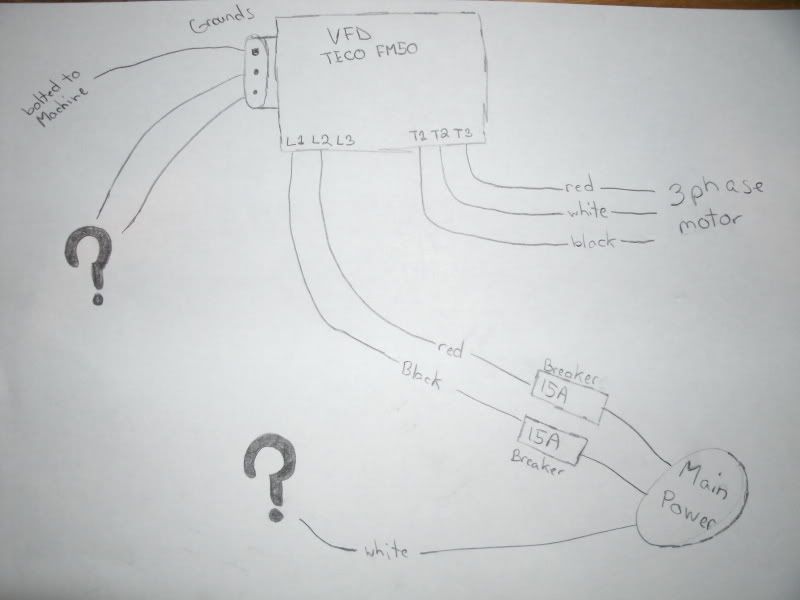
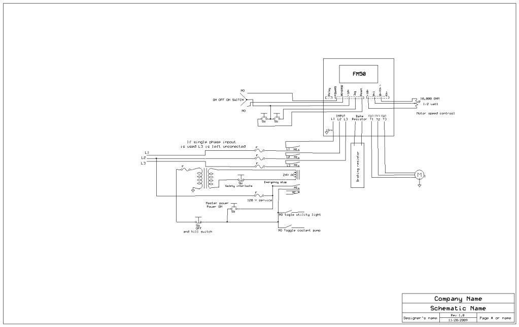
while reading the manual and searching the internet i started to really question how im wiring in my VFD's.

ill start off with the lathe. 3ph 3 hp motor. the vfd is a 3hp.

Picture780.jpg


Picture783.jpg


Picture782.jpg


Picture784.jpg


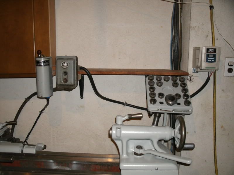
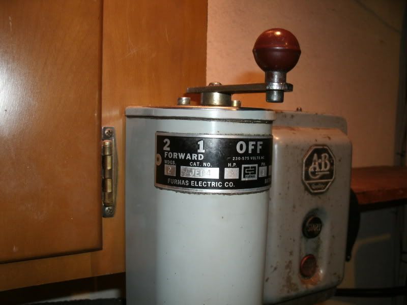
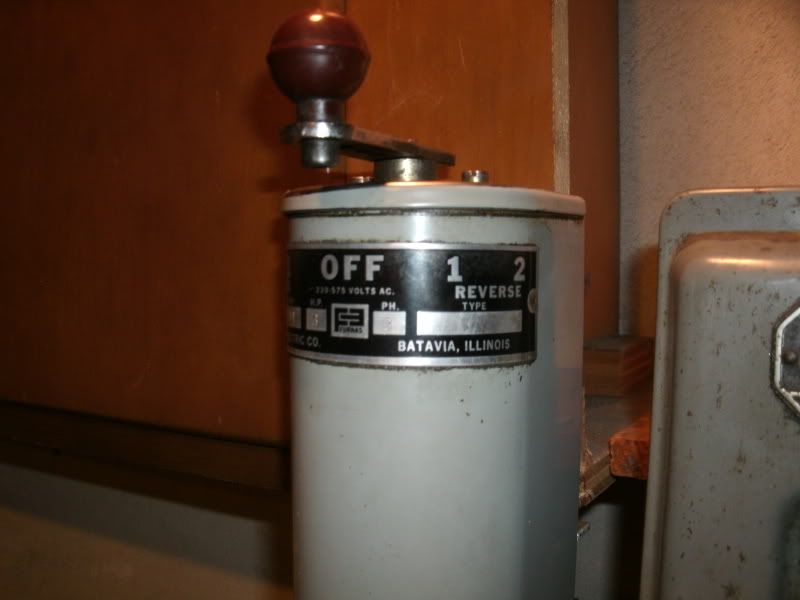
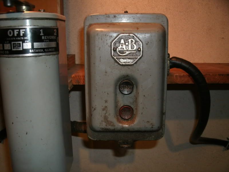
that 1 2 F and 1 2 R switch box is wired directly to that start/stop switch, which i just thought id wire to the vfd. but now imthinking thats completely wrong.

im thinking i need to remove that start/stop box and wire the 1 2 f/1 2 r box directly to the vfd and use a seperate switch to turn the vfd fwd/rev. but then how will that work ? ill have a fwd/rev switch on the vfd and on that second control box ? wont they clash together ?


second is my 1.5hp 3ph bridgeport mill. the vfd is a 2hp.

Picture787.jpg


Picture788.jpg


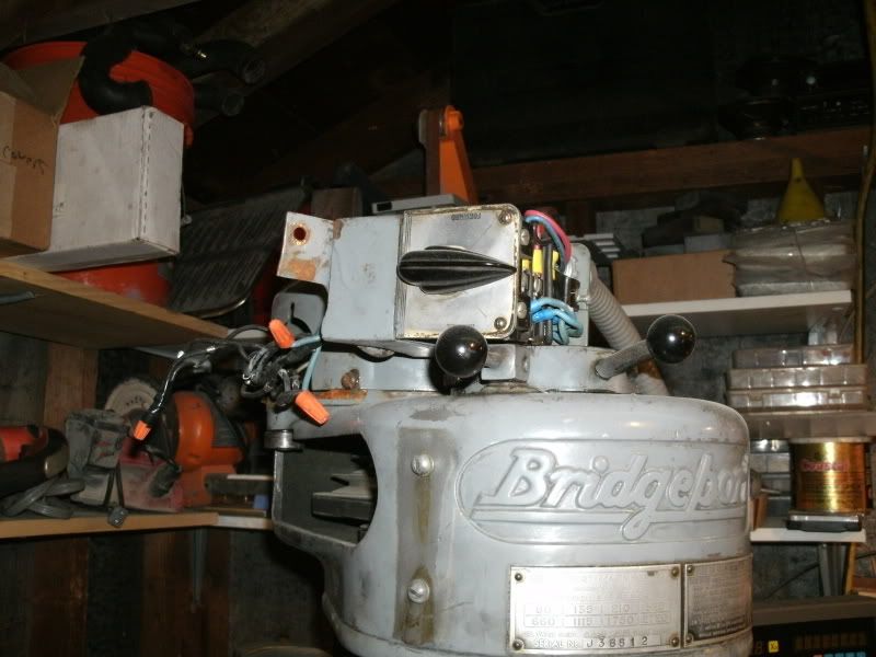
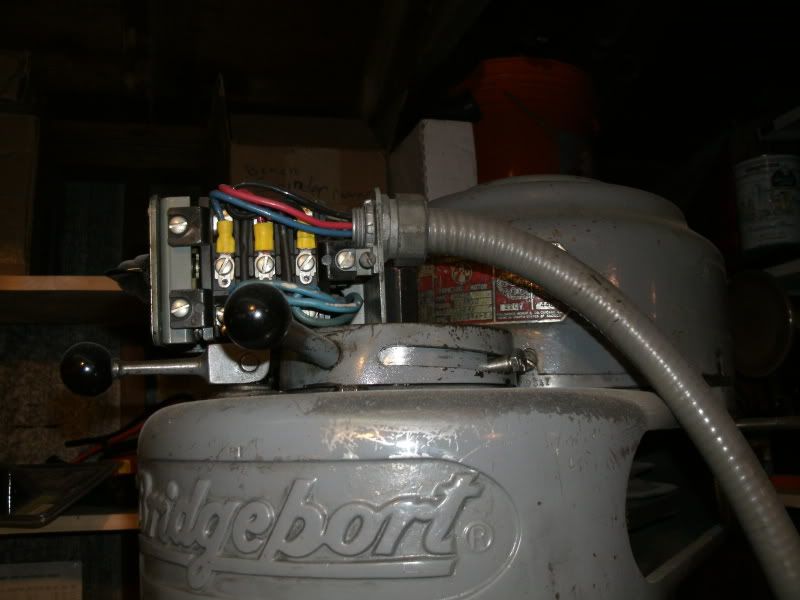
i dont have the switch box bolted to the motor but just look past that. for the mill do i just skip the switch box entirely and run a simple fwd/rev switch on the vfd ?


please specify which machine you are talking about wehen giving help. also what switches do you guys recommend i use to control the vfd's ? links to specific switches would be best.

lastly, where do i run the grounds from the vfd to ? do i just ground them to the steel of the machine ?
 
This is how I wired my lathe and mill using an FM 50 some of the relays are redundant but I have been using my lathe almost everyday for about a year and it works like a charm.

LatheMotorcontrolVer3-1.jpg


Mill

MillscamaticwithFM50.jpg
 
Ideally you can eliminate the pushbutton station, the drum switch, and the magnetic
contactors that the pushbutton station is connected to. Really all you need to
run the VFD is two position center off toggle switch and a 5K ohm variable resistor.

Oh you could wire up the PB station to run the VFD but it's overkill in terms of space.

Don't toss out the drum controller, that's a very special item made to run two speed
pole changing motors. Put it up for sale here and it'll go fast I suspect.
 
In a simple VFD install.

ALL RELAYS ARE REDUNDANT. NONE ARE NEEDED.

Mechanical switches for low power work have been replaced entirely by electronics.

The machine should have either a plug connection or a disconnect switch for Lockout. Input fusing required for VFD Input.

The problem with using relays/contactors is they stick... Are obsolete by the time they wear out, and add a whole cr@pload of unneeded wires to fight with.

With the right VFD, 1 phase + 3 wires in, 4 wires to motor. Around 1 multiconductor shielded low voltage control wire.

One 3 position toggle switch, one pot for speed control. I used a standard steel light switch box to BP motor wire box.

1 pot, 1 toggle switch and 2 holes drilled to accomodate both, in a blank steel switch box cover.

A couple more multiconductor wires, if you want to wire in apron switch, foot break, E Stop.

No control/light transformer needed on most installs.
 
if i stick with just the vfd ill have absolutely no idea what my rpm's are, ever. i calculate my rpm's to save bits. is there any tool that can read rpm's off of the mill or lathe to tell me what its spinning at ?
 
What???

All the VFD's I have installed, can be set to show HZ with nice bright LED displays on front panel.

With a VFD at normal 60 hz (50 for Euro) , machine spindle rpm is exactly like data plate on machine.

30 hz equals 1/2 data plate speeds, 15 hz equals 1/4 plate speed. 90hz is 1.5 times plate speed, 120 hz is twice plate speed.

For simplicity, I set my VFD to run from 15 to 120 hz.. Knob full left is 1/4 spindle speed, Knob straight up is 60 hz (normal machine speed) Knob full right is twice normal spindle speed.

Most people have a calculator in the shop.

NO EXCUSE TO NOT GET A VFD.

Some tooling might perform perfectly at 47 hz (other tooling at 29). The mechanical geartrain driven spindle speed, without a VFD/DC drive, could not get that close.

A VFD WILL SAVE TOOLING..

Got a chatter problem? Dial knob back a trifle.

Great when boring as hole gets larger, just twist knob down a bit.
 
as shown in the pictures ive already bought the vfd's.

im new to the this vfd stuff. i wasnt aware that the speed would directly go with the vfd's hz. that solves that issue.

you said i need 1 pot and a toggle switch. whats a pot and do you have a link to a proper one ? im assuming and 3 pole toggle switch will work ?
 
What kind of link? It's just a variable resistor. The switch is single pole double
throw, center off.

Did your VFD come with a manual, there's a great deal of good information in there.

You will need to read that to determine which logic terminals to connect the
speed control variable resistor, and the fwd/off/reverse toggle switch.

Also, for starting out, you can simply operate the VFD purely from it's front panel.
In that fashion, no extra parts are needed at all.
 
The printed TECO manual does not have all the info the CD does... CD is better, but still a poorly translated and written manual...

Teco should use a single turn 2k ohm or 5k ohm, linear taper potentiometer. 1/4 in shaft. Does not need to be a large multi watt unit.

Radio Shack, Digi key, Mouser, local electronics supply store.

Standard toggle switch as posted before, on/off/on 3 position single pole.

Get a nice, tight, quality pot and switch.

A standard steel power receptacle box with blank lid, makes a nice small control box. Easy to put switch and pot in, for remote control of VFD.
 
Right sorry about that. I always harp on that point, the paper manual is missing KEY
information about the wiring. The cd rom has the diagrams needed. Thanks for
bringing that up!

First time I did a Teco VFD, I was pulling my hair out right and left looking the
paper manual - for something that wasn't there!
 
Wiring

Hello all
Do not let these VFD mess with you. Wiring them is fairly straight forward. From a 220 single phase plug that will be plugged into a receptacle on the wall Wire single phase 220 into VFD (two wires w/ground ie L1 / L3 / PE(ground). Then wire 3 phase directly to the motor ie 3 wires / ground from the VFD. One wire from T1 / one wire from T2 / one wire from T3 to each leg of the 3 phase motor. Connect ground leg of motor to ground position on VFD. There the VFD is wired into the motor you can plug in the VFD for power, it will power up then you can use the on/off of the VFD to control the motor on/off along with the hz adjustment on the VFD to control motor speed.
Now for those of us with lathes we like to control them from the lathe apron. OK now we wire the forward/stop/ reverse handle on the apron to the external control positions on the VFD. Wire one wire from one side of the switch on the apron to the forward position on external control terminal on VFD. Then wire the other side of the switch on the apron reverse position to the external control terminal on VFD. Then wire the common of the switch on the apron to the common position on the VFD. There are directions with each VFD that show the wiring contacts for each wire position. Once you have wired the external switch on the lathe into the VFD you must go into the VFD programing and tell the VFD to except control from the external apron switch. Look in your VFD manual it will tell you how to do this. Here is a link to a youtube of my SB lathe VFD wired and working.:D
YouTube - South Bend lathe 7388

Now once you have this wiring done you may insert the 220 V on/off power switch between wall plug and the VFD. You then can pull power from the same switch to another on/off switch to power the 1/8 hp 220V coolant pump on the lathe. Also wire in a E-stop to remove power from everything. This is the row switches on the box to the right of VFD box in video. Using the terminal blocks make connecting the wires from each unit easier. The TECO VFD that I have also allows me to wire in an external pot. control to adjust the HZ. I have one on the box to the right however it is not currently wired into the VFD one must leave something to be done
Hope this does help. PM me if you have question I will try and Help.
Bill
 
Last edited:
From a 220 single phase plug that will be plugged into a receptacle on the wall
-1

The FM50 instruction manual states that A Power Disconnect or Circuit breaker must be installed between the AC power supply and the AC drive. The drive will function if plugged into a wall receptacle, but it will not be installed per manufacturers instructions, which is a code violation.

----------------
Barry Milton
 
I think the code says, as long as the receptacle is visible from the operator, that
qualifies as a disconnect.

However.

There really does need to be an overcurrent protection device, like a fuse.

Also be sure it's a 240 volt drive before connecting it to a 240 volt receptacle.

:)

Teco makes 120 in, 240 out drives as well.
 
Yep

Barry you are correct in reading the manual, however I find that if explained in the simplest form first people tend to catch on quicker. If you continued on with the thread you would see that wiring a disconnect (on /off switch) between plug and VFD is stated. It is just that one only needs to use a 220V on/off switch, not contactors, heaters or anything else. The correct circuit breaker ( read what your VFD requires) in the electrical sub box or supply box is protection enough for the VFD. The VFD itself will protect the motor. Now I am not saying if one so inclined has to wire circuit with another 500.00 worth of molded case circuit breakers (MCCB) and Cuttlerhammer contactors etc. it does make for a nice setup however just not needed.
I believe Jim you are correct in that if the plug is visible to the operator that may serve as a disconnect, need to read the code book again.
abarnsley just backing you up.
Just trying to help.
Bill
 
"I believe Jim you are correct in that if the plug is visible to the operator that may serve as a disconnect, need to read the code book again."

Up to and including 2 HP, yes. Over 2 HP, no.
 
This is what I use on a ~ 2hp or under, single phase VFD install. Breaker amperage to be installed, depends on the VFD manual instructions.

Square D QO2L30S Load Center:

Square D QO2L30S CP QO 30 Amp Surface Mount Load Center at HardwareAndTools.com

Mounts right on wall near machine and provides input overload protection for VFD. It has a tab to allow lockout of breaker.

Mine is plugged into a 220 receptacle (so I can move mill around), I still have a plug within sight that qualifies as a disconnect.

Breakers are not to be used a switches, unless rated for switching duty.

(sure see it done a lot though)

Fancier fused safety disconnect switches, are available.
 
"Fancier fused safety disconnect switches, are available"

I am always on the lookout for good, used fusible safety switches. Usually, for $10 apiece, or less.

I am retrofitting all my machines with such switches, even of they were equipped with magnetic motor starters and "three-wire control stations", either line-voltage or low-voltage (usually 24 volts), for safety purposes.

Several of my machines exceed 2 HP, so those safety switches allow for complete interruption of all machine power, after which the cordset, occasionally 50 A or 60 A, can be disconnected with no load.

I am reminded that that the mainframe computer systems which I used to design for a living were often provided by 100 A cordsets (Russell & Stoll-type), but that these cordsets were NEVER intended to be a disconnect. NEVER, ever.

Indeed, most such feeders were provided with MCCBs as their disconnect.
 
so the question nobody has answered yet.

where is the best place to ground these ? should i ground each vfd to its machine or just to the breaker box like every other ground ?
 
"...NEVER intended to be a disconnect. NEVER, ever."

That would be a heck of bang. YOu could probably get away with it. Once.

Sorry about missing the grounding question.

Basically you need to run a green wire from your power source for the vfd, to the
vfd, to the machine. The VFD will have a green wire grounding terminal on both
the input, and the output side.

So in my case the VFD is in an enclosure and I have a regular 120 volt cordset
that plugs into a convenient receptacle. That cordset has the green wire tied
to the terminal inside the VFD to ground the VFD itself, and that ground is carried
through to the output side and goes to the green chassis terminal inside the
motor junction box.

I also have a bonding strap to tie the machine frame to the incoming ground as well,
just in case.


Back
Top