What's new
What's new

230 V motor has volts at all three inputs, but no current

NRDock

Cast Iron
Joined
Jan 24, 2015
Location
Central Pennsylvania
I thought I was going to have a turning lathe today, but not yet :-(
My Pacemaker has an ancient Allis Chalmers 7.5 HP, 440/220, 284 frame motor, which I have seen run on 440 Volts.
I have just wired up a new 5 HP Spedestar drive (labled for split phase input). If any aspect of this combination doesn't work out, I'll get a 5 HP motor, which is still more than I'll ever need.

When I disconnected the old motor wiring, it was wired with inputs to wire numbers 1,2, and 3. The other six wires were paired 4 to 7, 5 to 8, and 6 to 9.

For 220 V operation I wired my new connections with inputs to 1 and 7, 2 and 8, 3 and 9. Wires 4,5,and 6 are tied together.

After figuring out the drive manual, I now have voltage at all three motor inputs, but no amperage output from the drive. The motor is making no movement or resistance to movement at all. The drive is indicating no error codes.

I'm guessing someone on here can give me some guidance to straighten this out.
 
Gotta have the Hertz man! Did you configure the drive for all the needed parameters? They usually don't work out of the box.

Stuart
 
Start by verifying with ohmmeter that the motor as-wired has conductivity from each terminal to all the others.
 
Gotta have the Hertz man! Did you configure the drive for all the needed parameters? They usually don't work out of the box.

Stuart
60 HZ. I watched it ramp up on the drive output display.
EE at work said most modern drives come set up fairly well, and I should just turn it on and go.
I scanned the parameters in the manual anyway, and the factory default settings looked reasonable.
 
Start by verifying with ohmmeter that the motor as-wired has conductivity from each terminal to all the others.

All I have on had is a little device that lights and chirps when positioned close to A/C voltage. I think my dad has an meter I can borrow later today, or I can run down to Lowes and buy one. Are there any particular features I should look for? I do know what Ohms are, but have no idea if the cheapest solution will work, or if I need something more specialized.
 
The wire connections look fine and the drive is very sensitive to load problems and would fault and show some type code if the motor internals were funky. Your display may be showing the frequency set in HZ but that doesn't mean the drive has been given the proper START command. I think it's a programming glitch.

Get that real smart EE at work to come over and solve your problems!

Stuart
 
My Friend,
Drives need two things to run. A go signal (start) and a direction of rotation. Both are supplied via the control terminal strip. Usually a 24v control signal. You need to place a switch or a jumper at this terminal so the drive know how to behave. Check the control section of the drive manual for proper information. Having full voltage at the output terminals is perfectly normal. Be careful, even if the motor does not run it will still electrocute YOU!

Only in 'remote'...otherwise should be in default to respond to panel control.

Stuart
 
You can very simply discover many things with a meter and the knowledge of how to use it.

I would never start something like that without having access to SOME way of verifying continuity and voltage.... Even if it's a light bulb and some wire.

You seem to have a "squeaker". OK use it.... set it (if it is settable) so it only squeaks when you are VERY close to the wire. Then carefully separate the wires (do NOT disconnect any) and try each set of MOTOR wires. If you get a squeak by them, and not until you ARE right by them, you can be reasonably sure the motor is getting something for voltage. It will NOT tell you how much voltage, because the high speed switching the drive does can give more indication than normal.

For anything more, you need a meter.

The essentials are ohms, and volts. It's *nice* and quite useful, if you can get a combo unit that will measure AC current with a clamp-on loop that is part of the meter. There are such meters, and they are not all expensive.

Basically, for ohms, you set to ohms and then check by touching the probes together. You should get some low reading, like a half ohm (most meters will not read a true zero). If so, then with NO POWER ON THE CIRCUIT, you can check the two points you need to check for continuity... touch one probe to each, and see what the meter reads. Dirty connections etc can cause bad readings, so if you do not get what you expect, be sure you have solid contact, and are not touching anything else besides what you are trying to measure.

For volts, set to volts, and touch one probe to each place you want to measure volts between. Since you do THIS wioth power ON< you want to be very careful to touch ONLY with the tips of the probes, and touch ONLY the places you want to. While touching, read the meter. If you have insulated "alligator clips" on the meter wires, you may be able to pre-connect, then turn on power. That's safer.

Current with a clamp-on loop is easy... set to current, pull out the probe wires from teh meter connections, press the lever that opens the loop, place loop over the wire, and let it close. Read the meter. Again, power is ON when doing that, so be sure not to blunder into anything else. The meter can be pre-positioned before power is turned on , and that's safer.

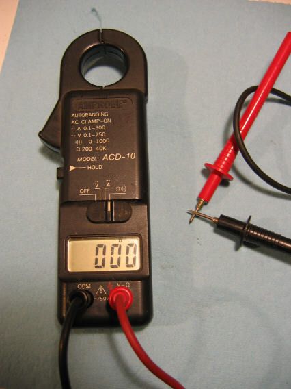
Here is a simple combo meter. Ohms, volts, and clamp-on amps. The lever at left opens the loop for amps. Here it is reading the check of ohms, with probes touching. It reads zero, because it is a one-size fits all values range that isn't really accurate at low ohms. Multi-range meters won't usually show zero on the lowest range. This one is nice because it also beeps for very low ohms (below 100 ohms for this one), so you don't have to read it to verify continuity (you would if you wanted to check an ohms value)


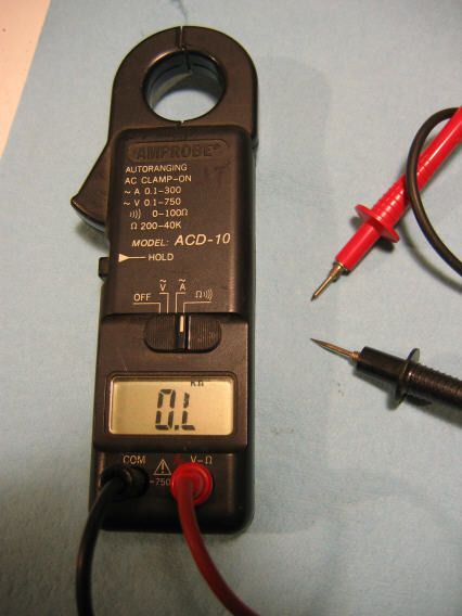
Here is what this one shows with probes open (no continuity)


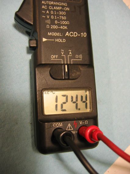
Measuring volts.... I have the probes in a 120V outlet. My volts are a little high it seems.


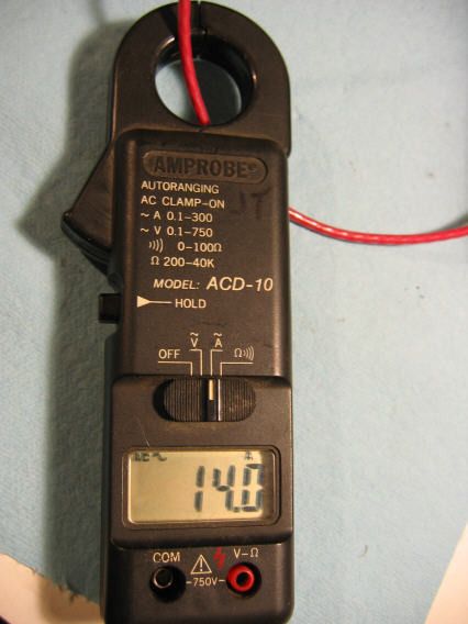
Measuring amps. Note, no probes in place, and the loop is closed over the wire I want to measure.
 
JST, thanks for your help. I picked up a meter this afternoon which is good enough to get started. We have guests arriving soon, so I'm done for the evening. I found a web site with instructions even I can follow to identify (wye vs delta) and verify a nine wire low voltage motor. First thing in the morning, I'll check it out. I suppose the best case at this point is that it is a delta winding, and I haven't damaged anything.
 
Whatever you do, do not let the smoke out of the VFD or motor. That smoke is apparently vital to proper operation, and once it escapes, it is gone forever. Good Luck, and Regards, Clark
 
While I don't know this for sure, I will say that Wye or Delta...won't matter to the drive, if all is programmed correctly, it should move the motor. If something is awry, the drive will shut down and do its very best to save its own skin. They treasure their magic smoke and protect it dearly.:)

Stuart
I've been assuming the drive didn't care whether wye or delta. I found the attached diagram, which also suggests that it doesn't matter to the motor for 440V, but it does matter for 220V. These are the diagnostic instructions I'll follow in the morning: http://www.theautomationstore.com/motor-tutor/
motor wiring.jpg
 
It matters to the motor, because there is a factor of 1.73 between the line-to-line voltage that a given motor will "take" without damage if connected delta (lower voltage) or wye (higher voltage). An example is 208V 3 phase... it is 208V measured delta, but it is only 120V from line to neutral. 120 x 1.73 = 208.

Obviously if a motor was intended for a wye connection on 208V, each coil would be good for 120V. Fine if connected wye, but if connected delta, each coil would get 208V, which it could not take. That always matters to the motor.

BUT, it is not an issue to the VFD, or to correct operation of the motor. The motor and VFD, if motor is connected correctly for the VFD output voltage, will not act any different whether it is a wye motor or a delta motor, all it cares about is being set up for the right volts, no matter what type connection that takes..
 
@#!@$%$%$^%&^*&(*(*&*&^^&$%@$#!##
My motor wires are numbered wrong.
I have continuity as follows
1-7
2-8
3-9
4-5-6
Since I've seen this motor run on 440V, it seems 1,2, and 3 must be correct. Then 4&7 are switched, 5&8 are switched, and 6&9 are switched. This arrangement still works on high voltage, but not on low voltage.
 
Success! The motor is working fine now that I've compensated for the incorrect wire numbers.
FWIW, according to the drive display, the motor is drawing 6.0 amps completely unloaded, and 6.2 spinning the chuck at 200 RPM. At 17 amps max, the drive should have plenty of capacity for anything I want to turn.
 
Whatever you do, do not let the smoke out of the VFD or motor. That smoke is apparently vital to proper operation, and once it escapes, it is gone forever...

Not entirely true. Once the smoke escapes you can replace it but it's hard to find and usually very expensive...:eek:
 
Success! The motor is working fine now that I've compensated for the incorrect wire numbers.
FWIW, according to the drive display, the motor is drawing 6.0 amps completely unloaded, and 6.2 spinning the chuck at 200 RPM. At 17 amps max, the drive should have plenty of capacity for anything I want to turn.

Excellent!

And yet another example of why having a meter is essential to doing electrical work like this.
 
It's pretty interesting that only 6 of the nine wires were incorrectly marked! Were these factory markings..crimped on steel markings?

Stuart


Back
Top