peterh5322
Diamond
- Joined
- Dec 15, 2002
- Location
- Monterey Bay, California
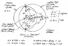
Referring to the attached diagram ...
The C-N-A phasor remains largely the same irrespective of load.
The values of the Cab and Ccb capacitors affect the magnitude of the N-N'-B phasor. The load affects this phasor, too.
There is a point at which, for a given load, N-N'-B is 208 volts, if C-N-A is 240 volts. This is the balance point.
If the load is lower, then there are too many VARs (volt-amperes, reactive) and N-N'-B will be greater than 208 volts.
If the load is higher, then there are too few VARs and N-N'-B will be lower than 208 volts.
Although it is usual to measure C-B, A-B and B-C, it is also possible, in some cases, to measure N-N'-B.
The single-phase line is supplying the real power as C-N-A.
The RPC's idler and its capacitors are supplying reactive power as N-N'-B.
Combining the real and reactive powers, at the load motor's terminals, results in the apparent three-phase power.
An RPC can "source" three-phase power, but it cannot "sink" three-phase power.
Therefore, an RPC is not a useful source of power for a load which regenerates three-phase power to the line during "regenerative braking" as only the A and C phases can sink such power.
A utility three-phase source can both source and sink three-phase power.
A Phase Perfect device can also source and sink three-phase power.