What's new
What's new

How to hook up a VFD.

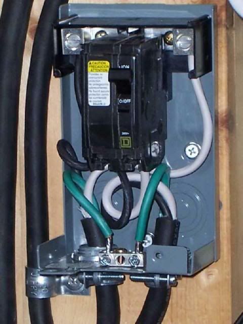
Since the drive doesn't have an On-Off switch, first run power from the wall outlet through a disconnect.

disconnect1.jpg


Then run the power cord into the VFD and make the line connections per the Teco instructions (terminals L1, L3, and PE). Connect the motor leads to T1-T2-T3 and run them to the motor. Use the wiring diagram on the motor & set it up for low voltage. Ready to go:D

The quick start guide will help: http://www.tecowestinghouse.com/Manuals/EV_Installation.pdf

--------------
Barry Milton
 
That is Step One. Once you have that part done, post back as you'll want to set the basic parameters (minimum freq, maximum freq, accel time, decel time, etc.) All these are called F Parameters in the Users Manual.

The first drive is always interesting. Change only one parameter at a time to see if you like the change - if not, adjust it slightly & try again. Pretty soon you'll have the drive configured just the way you want.

--------------
Barry Milton
 
Good answer, Barry!

Good answer, Barry!

Rob- once you have it set up and operational, study the wiring diagram on page 6, specifically terminals 9,10,11 (speed control) and terminals 4-8 (run/direction controls). To make best use of the VFD, use these inputs and basic switches and a potentiometer to remotely control speed and direction. Many guys will wire the run/direction controls into whatever motor-direction switch USED to control the machine... but you can put 'em anywhere, and put a knob on the pot so you have convenient speed control, while the VFD is still mounted in a safe, clean enclosure somewhere out-of-reach of flying tools, workpieces, chips, and swarf.

Programming information for those inputs appears on page 18 or so...
 
I'm also getting ready to buy and install a VFD for my home lathe w/1.5hp 3 phase motor. I plan using the TECO JNEV-202-H1.

Dave & Barry,
Am I understanding you correctly, the direction controls should be controlled in the VFD and not using the original forward/reverse control on the lathe? OR, does the power go first to a master power switch then to the VFD then the forward/reverse swich and then the motor? I want to do it right and make the best use of the VFD. However it would seem to control direction from the VFD may be more awkward. But may be that it would just take some getting use to and placed within easy reach.

thanks,
danny
 
Last edited:
it would seem to control direction from the VFD may be more awkward.
Danny,
As Dave said, the machine's switch will still control Run-Stop-Reverse, but it is connected to the VFD which allows the VFD to be directly connected to the motor. You'll still run the lathe just like before, which is what most people want, but with slightly different wiring.

On a freq drive, power is run to some type of disconnect, then to the drive, then to the motor - with no switches in between. Then connect the machine's switch to the drive so the VFD takes signals from the Run-Stop-Reverse switch to control the motor. And add a remote speed pot if don't want to reach for the drive each time you want to vary speed.

On some installations, it's easy to mount the drive where it can be used for all control functions. But on a lathe or mill, where your hand & brain are already familiar with control placement & operation, using the original switch makes more sense.

--------------
Barry Milton
 
Danny to put it another way, the power circuit goes from the power source (plug,
panelboard, whatever) to a disconnect of some kind, to some kind of overcurrent
protection, to the input terminals of the VFD. From there, you run the three phase
power directly to the load motor. No stopping anywhere else in between.

Any control functions, fwd/stop/rev, speed control, E-stop, etc are all handled
at the low voltage logic connections of the drive.

In the photo above, the square D breaker serves as both the disconnect and
the overcurrent protection.

Jim
 
Thanks Barry & Jim,

It is more clear now. Maybe if I had the instructions in hand I would have understood,...maybe. One thing I was not aware of is the control functions are low voltage. This helps much with my understanding. I was hoping to us the existing on/off push button switch, but the overload protection of the breaker makes much more since.

After I get the VFD I may be back with more questions.
thanks again,
danny
 
In the pic of the disconnect switch is that a regular breaker? Here is a pic of the dayton motor spec just checking to make sure the jnev-101-h1 will work. Thanks photo (17).jpg
 
WOW...and I thought I worked slow. 4 years to respond to a post and hook up your device! Must have been on the 'really' back burner Robert.:D

Slow Stuart the Numbskull!
 
Well it was really back burner i got all the parts gathered up and the my oldest son started Cub Scouts.Well long story short I ended up his leader, then the Cub Master and now the leader of my youngest sons den. And I am just making time to complete a few(seams like several hundred) projets.And this one is first. So here I am and i appearntly need more help than I figured. I awnsered my own question about the breaker.;)
 
Ok I have hooked up wiring and test run motor Now I need help programing the VFD. Any help greatly appreciated. The motor is turning the correct direction. I just need laymans terms of what to program. Right now i would like to program pot knob hook up run stop reverse control. My factory forward/rev is gone and aftermarket has been installed. not too confident on this part.

Thanks.
 
One thing you might need to confirm, my VFD instructions calls for quick blow fuses of the correct size, I was going to use a breaker as well and after seeing this in my manual I did some research and found that a breaker might not disconnect fast enough to save the VFD in some cases...so I used a disconnect with type T quick blow fuses ............


Back
Top