What's new
What's new

My First 5hp Phase Converter

nt1953

Hot Rolled
Joined
Sep 4, 2004
Location
Huntsville, Alabama
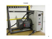
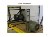
My First 5hp Phase Converter - now with pictures

I have just completed my first phase converter and I have parts lists, diagrams, and pictures. Unfortunately, the files are too large even when zipped. I generated them in Power Point, but have saved them as a slide show or a web page. Saving them as jpg files seems to loose too much resolution. If someone could help me post this, I will send the file or files. I also have some extra breakers as I bought lots from eBay.
 
Last edited:
I have just completed my first phase converter and I have parts lists, diagrams, and pictures. Unfortunately, the files are too large even when zipped. I generated them in Power Point, but have saved them as a slide show or a web page. Saving them as jpg files seems to loose too much resolution. If someone could help me post this, I will send the file or files. I also have some extra breakers as I bought lots from eBay.

You may have to load them to like photobucket, or something of that nature.

If ya want to shoot em over to me, I can upload em to my photobucket acct, and post em that way.

I'd be interested in seeing them.

EMAIL
 
Here is my attempt to get pictures loaded. This should be four of seven.
 

Attachments

  • Slide1.JPG
    Slide1.JPG
    66.7 KB · Views: 301
  • Slide2.JPG
    Slide2.JPG
    67 KB · Views: 1,158
  • Slide3.JPG
    Slide3.JPG
    94.5 KB · Views: 279
  • Slide4.JPG
    Slide4.JPG
    92.1 KB · Views: 354
Affirmation

A double check of the running caps on my home built 5HP RPC

70 microfarads between L1 and the mfg leg, and 75 mf between it's complement. Sure is close to what you have adopted. ;-)

Didn't check the line to line voltage, It's written down ...somewhere.

CalG
 
CalG
I decided that amperage was more telling than voltage. However, not everyone has a good clamp on ammeter while almost everyone has some kind of voltmeter that is adequate.
Thanks for the feedback.
 
You will shortly fry your NO switch contacts. The NO switch should not be connected to the load side of the contactor. The NO switch should only have the coil load on it.
 
CalG and Torque1st
The coil must be energized to hold the contactor in. If there is no connection where you suggest I remove the "dot" then the coil is deenergized anytime the NO button is not pushed. In the current configuration, when the NO is pushed, power is provided to the coil, and voltage is supplied to one leg of the motor. However, until the contactor pulls in, no current flows (contactor completes the circuit). So, when the contactor closes and completes the circuit, there are temporarily two current paths; one thru the NO switch, and one thru the contactor. Opening the NO at that point should be a low arcing event.

I can not see any other way to do this, but if there is one, I would like very much to know what it is before I build a larger converter. Please provide a diagram.
 
Yes, yes,, Over reaction on my part. A 240 V coil shold have not issues with the chircuit. Now I'm trying to get what Torque is getting at.

CalG


Back
Top