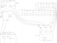
Hi guys. I recently acquired a Kondia Clausing CNC knee mill, model FV1. I have built a rotary phase converter and have good voltage but the spindle will not start, it tries but then pops a 30 amp breaker before the RPC or pops a reset in the machine control. Let me explain my RPC and see if maybe I have something wrong or if it is maybe just too small.
First I have a Louis Allis Pacemaker 3 hp motor type COG4B. I'm using a Cutler Hammer A10BN0 contactor switch for the start capacitor circuit. I'm using a knife switch and a push button for control. I have 240 volts from my breaker panel going to the knife switch, from there I pulled 120 from one side and the neutral to power the contactor with a push button. Im using both the 120's from the knife switch to go to L1 and L2 on the motor. Im using 120 from L1 to go into one side of the contactor, when it comes out of the contactor it goes to my start caps. I have 2 108 t0 130 330 volt caps wired in parallel. I then come from the other side of the start caps and go into another leg on the contactor, from there I come out the other side of the contactor and go to L3. The start system is working quite well. I have run caps wired between L1 and L3, I have a 30, 10 and 7,5 mfd wired in parallel. I have run caps wired between L2 and L3, I have 35,30,30,5 and 5 mfd wired in parallel. When I check voltage between L1 and L3 it is 245. between L2 and L3 is 242 and L1 to L2 is 240.
A friend that has built a few RPC's said that if I check from L1 and L2 to neural each should be 120, and L3 to neutral should be 260. I have 120 on L1 and L2 but only 210 on L3. Im afraid to go much higher with L3 because I think this will take me way over 240 volts, when checking from leg to leg. any comments or help would be greatly appreciated!


