What's new
What's new

Rotary Phase Converter Help and Troubleshooting

BSACafe

Plastic
Joined
Apr 8, 2015
Hi All,
I've used this site quite a bit for a resource to get all the necessary equipment and wiring diagrams for my rotary phase converter. I have it hooked up the way I have been instructed, or at least I think I do, but it doesn't seem to work. When I turn it on, the Idler Motor doesn't spin, it just buzzes and wiggles back and forth. Below are some pictures of the wiring.


The picture below shows the inside of the RPC box that I purchased, and how the start and run capacitors are wired.
Scan0002.jpg

This picture shows the instructions that were provided on how to wire it.
Scan0003.jpg

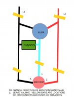
This picture shows how I have it wired. Note....I have a two pole disconnect switch between the 220 Panel, and the RPC Box.
Full Box - Wired.jpg

From everything I'm reading, it seems like the Idler Motor is getting the 220 power, but the start capacitors in the RPC Box aren't working to get it running. I've read that if you don't have start capacitors, you can spin the motor with a rope to get it a jump, but I don't want to do that. I must have something hooked up incorrectly in the RPC Box. Can anyone offer a little help, or what I need to do to test it?

Jeremy Hallworth
Saint John, NB Canada.
 
I have put together a diagram of the Rotary Phase Converter to see if I was hooking something up incorrectly. It must be a simple fix....I just can't figure it out.

My Garage Hoist.jpg
 
Hi Bob....I haven't seen the motor running before. I bought it from a friend and they have another one I can try. I figured I'd go through the wiring to be sure it's correct first.
 
I updated the schematic for how my wiring is hooked up below.
My Garage Hoist2.jpg

I've traced all of the wires, and compared it to the connections on this other diagram.
phase3.jpg

All of the connections are the same, with the exception that my box uses Dual Run Capacitors. That said, the green wire that comes off terminal 3 and goes to the run capacitors isn't on the second diagram.

I'm thinking it may be a bad idler motor like Bob suggested, but I thought these things lasted "forever." Does anyone know how to check the idler motor to verify it will work? I tried tying a rope around it and spin it to give it a jump start, but it just went back to bouncing back and forth. It does spin freely. Any help is greatly appreciated.
 
So rope start it, and see if it goes.

if so, your capacitor start isn't working. Check wiring and see that the start relay is closed to start, and not wired normally open

If not, the motor has an issue or is wired wrong. A coil wired backwards on a dual voltage motor can cause similar problems. for instance.

Make some ohmmeter measurements and see if a completed circuit exists thru the motor, never mind the connections.

You gotta get more "hard information", guessing isn't useful.
 
This is probably silly but you drew one leg in green and green is usually reserved for ground. I don't see a ground drawn in another color. I'm looking at this on my phone through bifocals so I may be missing something. I've never used run caps on a rpc but I'm sure they balance the three legs and make smoother power.
Rick
 
I have had a working system for years. I do NOT have caps connected on between both sides of the 3ed leg to the line like you do. Just on one side only. I use run caps only permanently connected and they are enough to start the rotation of the idler. Will make a ugly dwg in a moment.
 
I've done some more testing...here's what I did and found.

I did a simple ohmmeter to test on the idler motor, L1, L2 and L3 to ground, nothing, then L1 to L2, L1 to L3 and L2 to L3 all within 10% of one another....perfect.

I then was comfortable to hook the motor direct to 240v, and use the rope method for spinning. I did this in the rotation marked on the rotor, and as soon as I gave it power it was resisting to spin (like hitting the brakes.) I then wound the rope in the opposite direction, gave it a spin and connected power. It started right up, and spun very quietly and smoothly. I'm now confident the motor works great, but is reverse rotation.

So....it's definitely a problem with how things are wired up.

Note...I only used green on the diagram below to make it easier to see. All items in the system have a separate ground, but I didn't put that in the diagram.

Also, this was a box that I bought from ebay, and it's how it came wired. I hooked power to it, as instructed, but obviously something isn't correct.

Here are the issues that I see.

1- the rotation of the idler motor is reversed. Will this be a problem with generating three phase power? Should this be corrected?
2- there is something hooked up incorrectly preventing the start caps from running. When hooked up per instructions, the idler motor just buzzes and dances.

I mentioned above that the run caps are Dual run caps. I have never seen these used in other RPCs, so I don't know if this is causing the issue with how it's wired.


My Garage Hoist2.jpg
 
Trying to upload a larger picture.

I've traced the lines, and just can't figure out what to try next.

I'm sure it must be a simple wiring error....any advice is appreciated.

My Garage Hoist3.jpg
 
I've gone through the wiring diagram of the RPC box and it seems to be correct. It must be how the Idler Motor is hooked up. It keeps jumping back and forth when I put power to it. I will try a different connection.
 
I don't see the resistor across your start caps.

I built one and the fact I put it in makes me think it was needed, because I would generally cut out stuff that wasn't essential to the function.
 
I don't recall seeing resistors across the start caps either. I will have to check. Is this possibly what would cause it to not run?
 
I don't recall seeing resistors across the start caps either. I will have to check. Is this possibly what would cause it to not run?
Probably not.

Let's think about what you are trying to do.

Don't think about the run capacitors, they don't have anything to do with what you are trying to accomplish (they are just to balance the voltage once it is started) (and don't worry about rotation)

You are trying to get voltage to all three legs.

You already have voltage to leg 1 & 3.

You are just trying to charge the capacitor and discharge it to the second leg.

Leg 1 is charging the capacitors.

then when the contactor engages it should send the voltage to leg 2.

Is the contactor engaging?

I would guess when the relay sees power on terminal 5 it initiates a time sequence that drops the entire start circuit out in a few seconds.

Edit:
If the contactor isn't engaging, remove the power(all of it) put the wire on from terminal 2 on with terminal 1. This is going to jump out the relay. When you plug it back in, the contactor holding coil is going to be getting 220 volts and should make. and the motor should start. If it does, un-plug it and take that new piece of information and think on it.


I TAKE NO REPONSIBILITY for bypassing the relay as suggested in the edit.
 
I understand everything you are saying....and I think you are onto something Grumpy.

I'm not 100% confident that the contactor is engaging. When I turn on the power, I see a small spark inside the screw hole lug in contactor T2. I've attached a picture with an arrow pointing to it. Would this mean that there's a poor connection, and it's arcing? Could it be as simple as a loose screw?

IMG_4930.jpg
 
The terminal has to be tight and you have to know if the contactor is pulling in.

You can run a wire thru the contactor L2 / T2 (not currently in use) (so you don't have to be so close to the live power) and ohm thru the empty contacts when the contactor should be engages.

If you are having problems with contactor L1 / T1. You may also swap the wires from the contactor L1 / T1 to L2 / T2
 
Grumpy,

I have verified that the terminal is tight inside the contactor.

For testing do I run a jumper wire direct from T1 to L1 and then measure ohm through T2 and L2 with the power off? Or do I put the power on?

I just checked for ohm from L1 to T1 and L2 to T2 with the power off and didn't get any change on the meter, so that would mean that the contactor is open with power off.

Also with it all hooked back up to power through the RPC box, I am no longer able to rope start it. I tried winding the rope in both directions, and as soon as I turn the power on, the motor slows to a stop immediately.

My Garage Hoist3.jpg


Back
Top