What's new
What's new

Two Speed Motor as Idler??

Denny Graham

Aluminum
Joined
Sep 1, 2004
Location
Sandwich, IL
Well I'm new here and I've been reading and downloading for the last three weeks. Soooo, I think I know just about enough to ask a few questions now, without sounding like to much of a dutz!
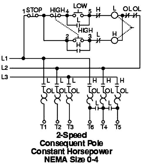
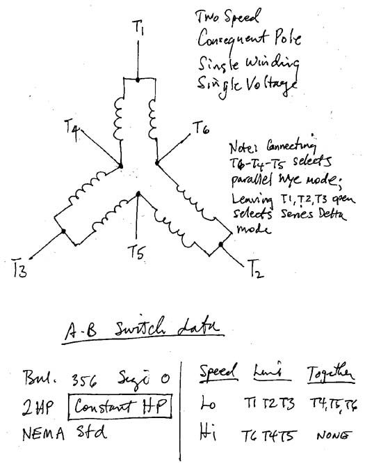
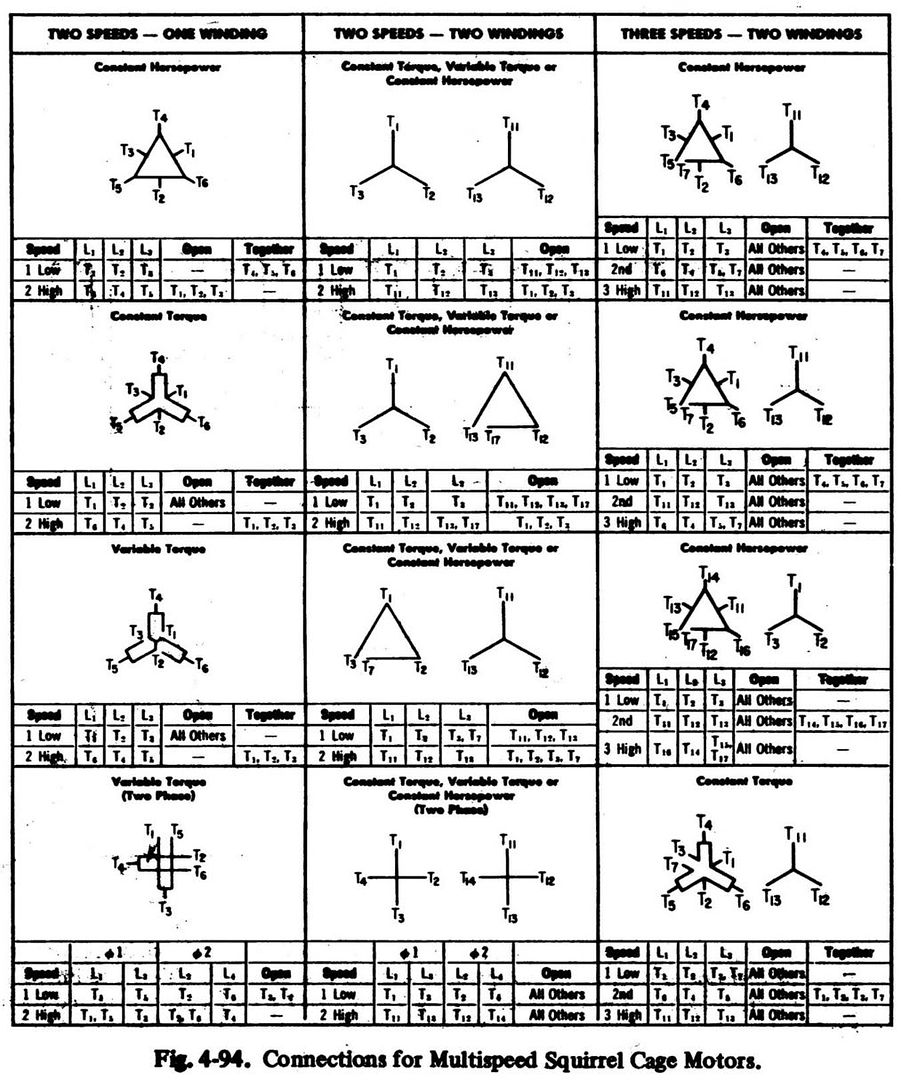
I would like to use a big old finned, cast iron, Peerless 2hp, 3ph, 220v, 5.2/6.2a totaly enclosed motor off of a spindle sander as an RPC. This is a two speed motor (3500/1750rpm) and was wired to a drum switch for Lo/Hi. The motor has two sets of wires that ran to the switch. Set1= T1,T2,T3. Set2= T4,T5,T6. I'm assuming that one set is for Lo speed and the other set is for Hi speed. I have no wiring diagram to referance to so I'm not sure what's going on with the coils.
My question is, can I use this motor for an idler and would I just use the 1750rpm set i.e. T1,2,3 for my converter? If so would I just tie T4,5,6 togeather? I am reading 3.6 ohm between any pair of T1,T2,T3. Also 3.6 ohm between any pair of T4,T5,T6. There is also some sort of internal connection between set1 and set2 as I get continuity between the two sets also.
I will probably use this RPC for a 1hp Bridgeport mill. After I play around with this ($10) 2hp motor and get a better feel for RPC's and ballancing, I will attack a (much more expensive)7.5hp 1740rpm RPC. I bought the 7.5hp idler to build a larger unit for my 2hp mill and any other 3ph equipment I may add to my shop.
Thanks in advance guys.
Denny Graham
Sandwich, IL
 
Some analysis is in order.

If there is continuity between T1, T2 and T3, but not between that set and T4, T5 and T6, then the motor is a two winding motor, and most probably a Wye/Wye motor.

If there is continuity between T1, T2, T3, T4, T5 and T6, then the motor is a single winding motor, and most probably a "constant torque", "consequent pole", series Delta/parallel Wye motor.

(Six wire, two speed motors are also available in "constant horsepower" and "variable torque" models, but these are quite rare).

The goal should be to connect the motor in that manner which gives it the higher of the two possible HP ratings.

Should that connection be the higher of the two possible speeds, then so be it.

If the subject motor is presently installed in a machine, then tracing the motor leads to the control could shed some light on its type, because if it is indeed a "consequent pole" type, then in one connection three of the motor's leads will be shorted together, while in the other connection these will be opened and insulated from one another.
 
Morning Peter,
Sorry if I wasn’t clear in the post above, I’ll try it another way.
There are two sets of wires coming out of the motor as follows;
1)T1, T2, T3 there is continuity between any pair in this set, they all read (3.6ohms).
2)T4, T5, T6 there is continuity between any pair in this set, they all read (3.6ohms) also.
There is continuity between the two sets as follows;
1)T1 to T4=2.2ohm, T5=4.0ohm, T6=2.3ohm
2)T2 to T4=4.0ohm, T5=2.3ohm, T6=2.3ohm
3)T3 to T4=2.3ohm, T5=2.3ohm, T6=4.1ohm

The diagram inside the Allen-Bradley drum switch shows;

Bulletin 365 Size 0
2sp-Constant H.P.
NON-REV

NEMA STANDARD
SPEED L1 L2 L3 TOGEATHER
Low T1 T2 T3 T4, T5, T6
HI T6 T4 T5 NONE
I don’t know how to interpret what this means.
I’m not an electrician or an EE so when you talk about the application of Wye/Wye or Delta/parallel Wye I’m really lost. I under stand what the Delta and Wye coil arrangement is but I don’t understand how or why or when they are used that way. I’ve been reading about consequent pole type motors since you mentioned them Saturday but it’s not clear just what that means.
The motor plate says nothing about it being dual horsepower, it only rates it as a 2hp, 2speed.
The plate shows the dual Voltage and current ratings but under the HP it’s only rating is 2hp. It seems to me, that the combination of drum switch diagram and motor plate would indicate it is a constant horsepower motor but that is why I am here, I just don’t know enough about motors to figure that out.
I hope this is enough information to analyze how the motor is/should be wired. I would like to use it at the 1740rpm speed if possible to reduce noise and current draw at startup.
Again my load on this RPC will be a 1hp single speed reversible motor.
Thanks,
Denny Graham
Sandwich, IL
 
The information provided by the continuity check is confusing and incomplete.

However, we can make some sense of the situation from the nameplate data on the Allen-Bradley drum switch.

The clues are these: constant HP; the connection of T6-T4-T5 during low-speed operation (with lines going to T1, T2 and T3); and the lack of connection of T1, T2 and T3 during high-speed operation (with lines going to T6, T4 and T5).

This means the motor is indeed a "consequent pole" motor, and that it is indeed "constant HP". Or, at least the manual starter is "constant HP".

Here is the schematic diagram of a Square-D consequent pole constant horsepower starter. This is a magnetic starter, whereas yours is apparently a manual starter. However, the theory is the same, and the application is nearly the same.


C-P_Const-HP.jpg


Since the starter is specified to be constant HP, we can assume that the motor probably does produce the same power at both settings.

Therefore, you would connect the idler for low HP, which is your expressed preference.

So, to more-or-less permanently connect the idler for low HP, connect T6-T4-T5 together, and insulate them, and connect the line to T1, T2 and T3.

(Should the performance not be as desired, more-or-less permanently connect wire the idler for high HP, leaving T1, T2 and T3 unconnected, and insulated, and connect the line to T6, T4 and T5).

So, connect the motor as specified above, and then utilize it as you would any three-phase idler.

The apparent inconsistency between T1, T2 and T3 and T6, T4 and T5, in low and high speeds, respectively, is due to the motor having only one winding, and also due to the additional poles required for low-speed operation being "consequent" and not actual poles.

Consequent pole constant HP motors are not very common, and are usually found in special applications. Most consequent pole motors are constant torque, for which the connection diagram is different.
 
"There are two sets of wires coming out of the motor as follows;

"1) T1, T2, T3 there is continuity between any pair in this set, they all read (3.6 ohms).

"2) T4, T5, T6 there is continuity between any pair in this set, they all read (3.6 ohms) also.

"There is continuity between the two sets as follows;

"1) T1 to T4=2.2 ohm, T5=4.0 ohm, T6=2.3 ohm

"2) T2 to T4=4.0 ohm, T5=2.3 ohm, T6=2.3 ohm

"3) T3 to T4=2.3 ohm, T5=2.3 ohm, T6=4.1 ohm"

Based upon the above posted winding/wiring diagram, the above quoted resistance measurements make complete sense.


Consequent pole motors are popular in machine tool applications as these can provide two speeds, related 1:2, with only one winding, thereby conserving "slot space", and providing greater HP for a given frame size.


Four speed motors are known, but as a consequent pole motor inherently contains a Delta winding, a T7 lead will be found on each winding, to be used when opening the Delta when the other winding, and set of speeds, is being used.

Such a four speed motor could have wires labeled: 1T1, 1T2, 1T3, 1T4, 1T5, 1T6 and 1T7; and 2T1, 2T2, 2T3, 2T4, 2T5, 2T6 and 2T7.

Such a motor could provide four speeds while consuming no more slot space as a two speed conventional motor.

But, I've only seen such four speed motors in industrial wood turning machines.


When three speeds are required, two speeds are usually provided by a consequent pole winding, while the third speed is provided by a conventional Wye winding.


Back
Top