What's new
What's new

Looking for a floating head for my router

macgyver

Stainless
Joined
Aug 2, 2012
Location
Pittsburg, KS
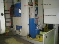
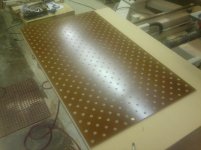
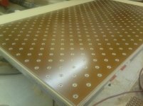
Hi guys, I just did a job where I engraved a design on a 4x8 ft sheet of acrylic and it needed to be very close on depth and it showed some imperfections in my table and spoil board. I have a plan to fix this but it made me think about a floating head or tool that I could use.

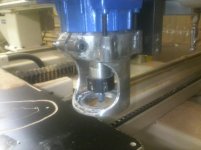
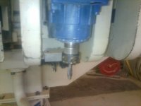
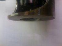
What I am looking for is a tool that has a follower foot that will run on the top surface of the part so that my depth of cut is the same no matter how worn out the spoil board or if even the material itself is inconsistent. I am only coming up with ones that are spring loaded and the depth of cut is dependent on hardness of the material and strength of the spring. I think the only way it will work on the materials I want to cut is to have a contact 'foot' or follower that rides on the material.

I vaguely recall seeing something like this on a router cutting ply at IWF many moons ago, but I am not having any luck finding it now. Have any of you seen one?

Thanks for the help,
Jason
 
Benz makes such an aggregate. Probably Techniques also. Will your router accept aggregates?
We've run a lot of plastic doing signage. Always surface the spoil board first. As long as your vacuum is sufficient to hold whatever thickness you are using flat,you should have no problems w/o the expense of an aggregate ($10,000+-!)
 
My router is not setup to take aggregates. Even if it did, I'd probably not be able to afford them. I had a couple agg heads at my old job and they are nice to have though.

I typically get the results I want without much trouble, but there are times that the last little bit that a floating head would take care of would be nice to have in the toolbox. I did find a you tube video of one on a hobby machine, their setup actually held the hand router that they were using for their spindle so the whole thing floated. I'd rather have something that I can chuck up in my spindle and do the floating there. I have some ideas rolling around since watching that video.
 
What I have in mind is a spring loaded tool, I don't have any fancy lasers etc on my machine. Thinking through it, I figure I would program as usual for a certain depth of cut, then if there is any variance within the material that is within the travel of the floating head it would compensate for it. Using a 45deg v bit even a few thousandths change in depth is easy to see in the final part.

Here is the video that I referred to in the last post. The setup/tool is at app 15 sec in and then in operation at app 40 sec in.

STEPCRAFT FLOATING HEAD - YouTube

I have been busy so haven't figured out a way to float the cutter without the spindle like in that video without spending a ton of time making something with a collet and some splines or keys and such.

The largest collet I can use on a main spindle is 1" and 1/2" on the piggyback spindles. I could pretty easily have an anti rotate arm built into it, there is alot of bracketry around the spindles for dust collection and such.

Worst case I guess I could make what is in the video and just mount it next to my oem spindles on the big Z plate.
 
I have some National Distribution (brand) tap holders that might be "convertible"?
Went to check one, and it is loaded the wrong way. Solid for pushing, spring tension comes into play when pulling.
It might be possible to take the internal spring out, and put a small one on the OD so it floats within a small limit.

integral collet holds 3/8", can be sleeved smaller. shank is 3/4". Max diameter at nut is probably less than 7/8"

If you want to try to modify one send me your contact info again and I'll put one in the mail.

ehmcofab at g mail dot com

smt
 
Ok, as I mentioned in another post, I am looking into this again. I had a 'duh' moment today and realized that the piggyback spindle is a good candidate to use as a floating head. It is on a THK slide and has an air cylinder that activates it into cutting position just like the main spindles, but it is much smaller and would be easier to get a stop shoe or collar onto it. I messed with it a little this afternoon and it looks like I can put a valve in the top side air line of the air cyl and shut off the air and then just the weight of the spindle mech is holding it down. I think that it would work great for this phenolic job I have at the moment and also for any future engraving jobs.

One of these days I'll get a proper picture of it, in this pic you can just see the bottom of the cylinder that I would unhook. The yellow dust shroud mount is off and I could probably make a shoe bolt in place if it.
 

Attachments

  • 805q drill head with text.jpg
    805q drill head with text.jpg
    86.7 KB · Views: 213
That spring loaded head in the video looks easy to make. Do you need a 7hp spindle for engraving acrylic, seems it would be kind of heavy. I'm wondering if you wouldn't have problems with chips getting between the contact shoe and the material, and marring the surface of the acrylic?
 
Richard, no I don't need 7hp, but it is much smaller than the 12hp mains.

I may have to deal with chips, not sure. So far I process all the acrylic with the paper still on it so I don't think it will be big problem.

Right now my main interest is for phenolic counterbores and I think the weight will be an advantage in this case.
 
What do you think of using a thrust bearing for the rolling shoe?
Good dust collection should keep the area clean, and or an air blast?

Would like to see it set up if you get the time to assemble and test.
 
My initial thought or plan is to use delrin as a contact shoe. I have a bunch of it on hand and I can turn a piece on the lathe and give it a flat in the center around the hole for the cutter and then make a smooth transition to the outer diameter. I think that would be the simplest to start with. Almost everything I'd be cutting other than the phenolic will have a protective film still on it.
The customer was happy with the table top I delivered yesterday, so they sent me back with 3 more sheets to do, so this is on my to do list next week.
 
I once had to move a large chuck around on a granite surface plate and then clamp it very tightly. The design we came up with was a floating platform (about 5" in diameter)that operated similarly to an air hockey puck, but in reverse. The chuck was supported by a plate with a number of concentric grooves milled in the bottom. Holes in the grooves communicated with cross holes drilled parallel with the surface plate. Very flexible tubing ran to a set of solenoid valves which connected either pressurized air or a vacuum to the "air hockey puck". When pressurized, the heavy chuck floated very nicely at a very constant height of several mils. When the chuck was in position, accomplished with a large precision X-Y sub micron translator system, The solenoid valve would switch off and the vacuum was applied. This locked the chuck to the surface plate VERY rigidly. This was part of an extremely precise lithography machine used in researching resists. Stability of the chuck in the nanometer range was achieved. Temperature effects and other environmental issues of course had an effect in the long term, but the air/vacuum arrangement was stellar at providing an essentially friction-less bearing between the chuck and the plate.

I know little about the router issues you face, but rather than having a physical bearing object maintaining spacing above the plastic sheet, perhaps using such a pressurized puck would have some benefits. Not the least would be a reduction of scratch potential and friction. Piggybacking an air cylinder operated lifting mechanism which references the puck would allow very precise control of tool depth. Most likely the vacuum option to lock the tool in a fixed position would not be necessary.

I hope that this is helpful.

Michael
 
Got to spend some time on it this week, so far so good. It doesn't look like much, very similar to a hand router base. I was being cheap and used what I had on hand, so it took longer to find it all and figure out what would work with what I had. I came up with a collar to clamp it to the spindle and then figured I would need a way to adjust depth of cut more precisely than just sliding the collar, so I put some bosses on the collar to run set screws up into the bolt heads on the spindle. It doesn't work too bad, I loosen the collar enough to slip and run the set screws in or out and clamp it back. I still need to make a wear plate for the bottom and I might paint it.

As for the spindle, I need to put a valve inline to the top side of the cylinder, right now I just unhooked it and plugged it, it does mean I have to manually drop the spindle the first time it calls it up in the program, but that is not a big deal right now.

The first job it will do is cutting a counterbore in phenolic sheet, the last part I ran there was a 0.030" difference in thickness across the sheet and the customer needs the counterbore within 0.005" from flush, the insert that fits in the pocket can't stick out.

I also just did a job where I engraved some 1/4" x 6x7 ft steel sheets and it was wavy as well. I had to reset the tool length offset for every word to maintain the same DOC, so I hope to use this on that job as well if it comes back.
 

Attachments

  • 0405171946.jpg
    0405171946.jpg
    80.8 KB · Views: 258
  • 0405171946a.jpg
    0405171946a.jpg
    97.1 KB · Views: 290
  • 0405171946b.jpg
    0405171946b.jpg
    99.2 KB · Views: 140
  • 0405171948a.jpg
    0405171948a.jpg
    97.4 KB · Views: 134
Just got done running the big sheets this week. The attachment I made worked out really well. Made these parts a pretty easy job, just took awhile to run.
First sheet, 429 holes, 2nd 238 holes and last 2 had 382 each. Nothing like a couple hour cycle time to get other stuff done in the shop.
 

Attachments

  • 0321171739a.jpg
    0321171739a.jpg
    89.6 KB · Views: 110
  • 0321171740a.jpg
    0321171740a.jpg
    92.1 KB · Views: 101
macgyver, does this have any axial compliance, or does it just serve to flatten out wavy material? Asked another way, will this work on material of varying thickness, rather than constant thickness but bad flatness?
 
Jason,
No pics of the shoe?
How did it work with chips/debris?
What if the connection between the router lift had some room to slide, so that when lowered the ram would overtravel and the router would stop on the sheet, when lifting up it would take an extra inch to engage the ram nut? This would allow you to operate the unit automatically I think?
I am sure you could figure out a way to lock the ram quickly for normal operations. If for some reason you needed more pressure then a spring could easily be installed.
Nice to see concept and completion.

Cheers,
Michael
 
This setup moves axially or vertically with the material thickness, that was the intended purpose. The material that I will be using it on most won't flatten out, it is either varying thickness and/or just too thick/strong to be flattened out. So I set the depth of cut with this gadget and the router spindle floats just like if you were to using a hand router with a base on it. Hope that helps explain it.

Micheal, the chips were not a problem, I had a dust collector hose as close to it as I could, so I think that sucked up most of it. I checked the depth frequently and it was staying consistent. I thought I had a pic of the shoe, but don't. It is just a 3.5" dia delrin washer app 3/8" thick. I drilled and coutersunk for some 8-32's to hold it on the bottom and chamfered the perimeter app 1/8".

As to operation, all I did was unhook the air line to the top of the cylinder so there is not any pressure clamping it in the down position like normal, it is just gravity, so far that is enough. The spindle motor and everything on it are heavy enough to get it done. To return it to normal will be to just plug the line back in and unclamp the gadget.

I am running it just as you described, I am programming it to over travel and the attachment I made is stopping it at the DOC I want. The spindle just floats on its THK slide while cutting. It is all automatic except for the initial drop of spindle at the beginning of the program. Since I unhooked the air line, it doesn't have anything to push it down into 'activated' position. I just push it down by hand and once down it does its thing til the end of the program.

Jason


Back
Top