What's new
What's new

Milling on the lathe...again..pics

Ray Behner

Diamond
Joined
Mar 27, 2009
Location
Brunswick Oh USA
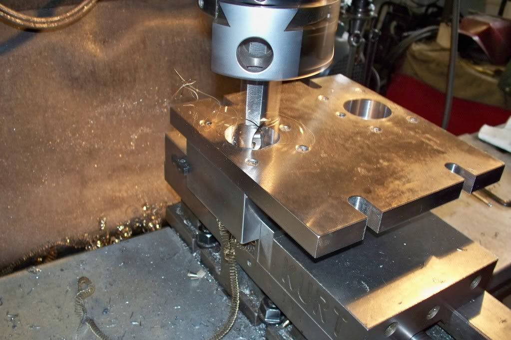
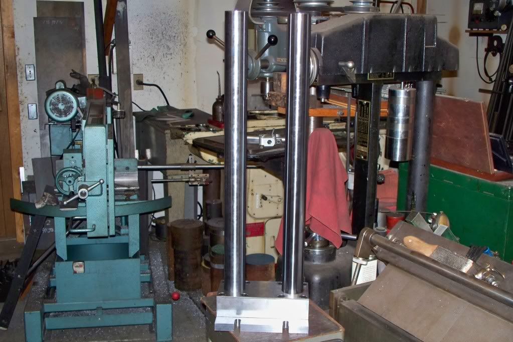
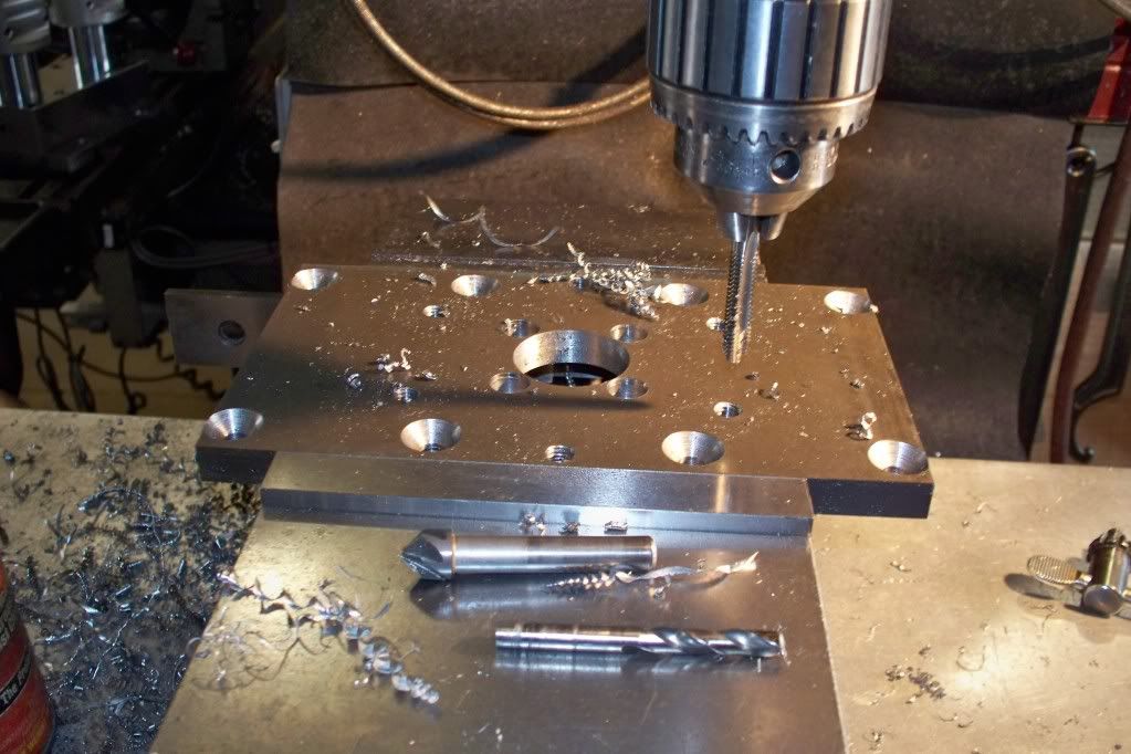
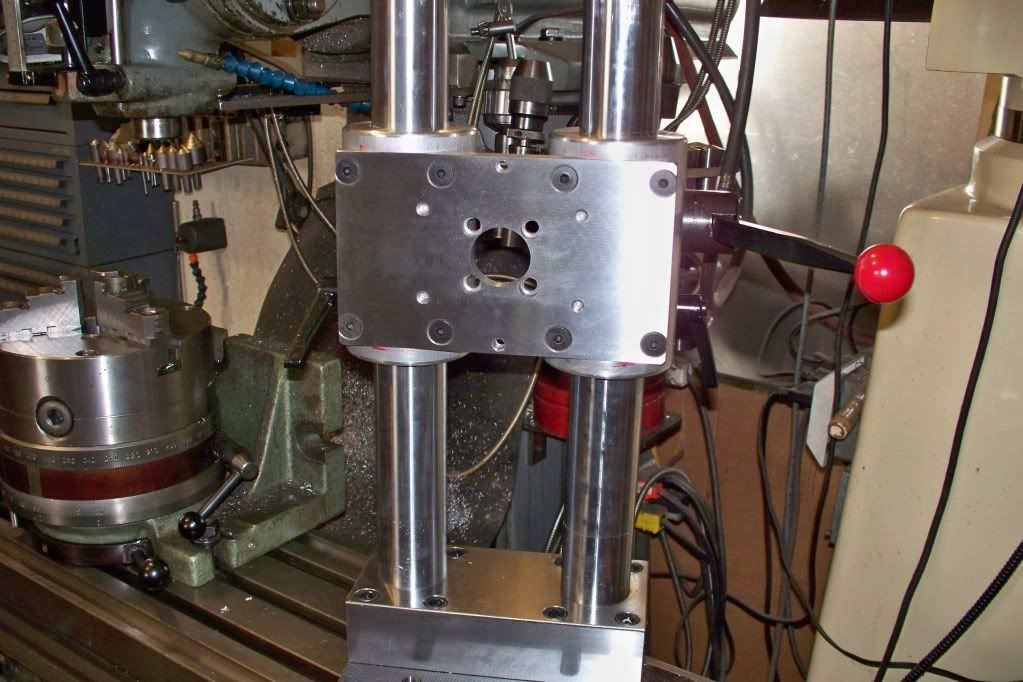
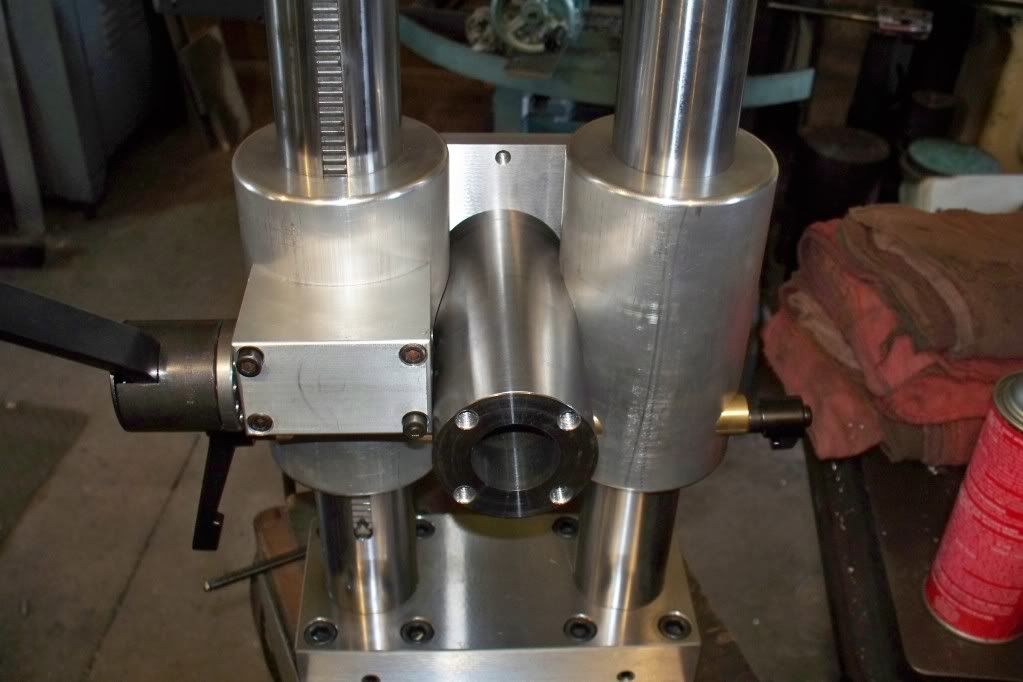
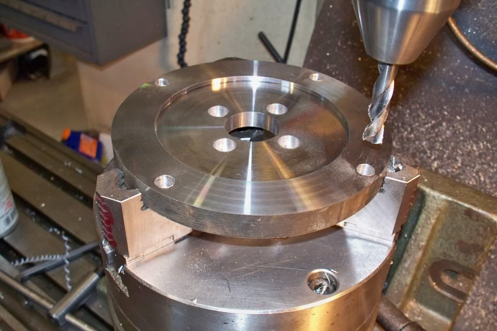
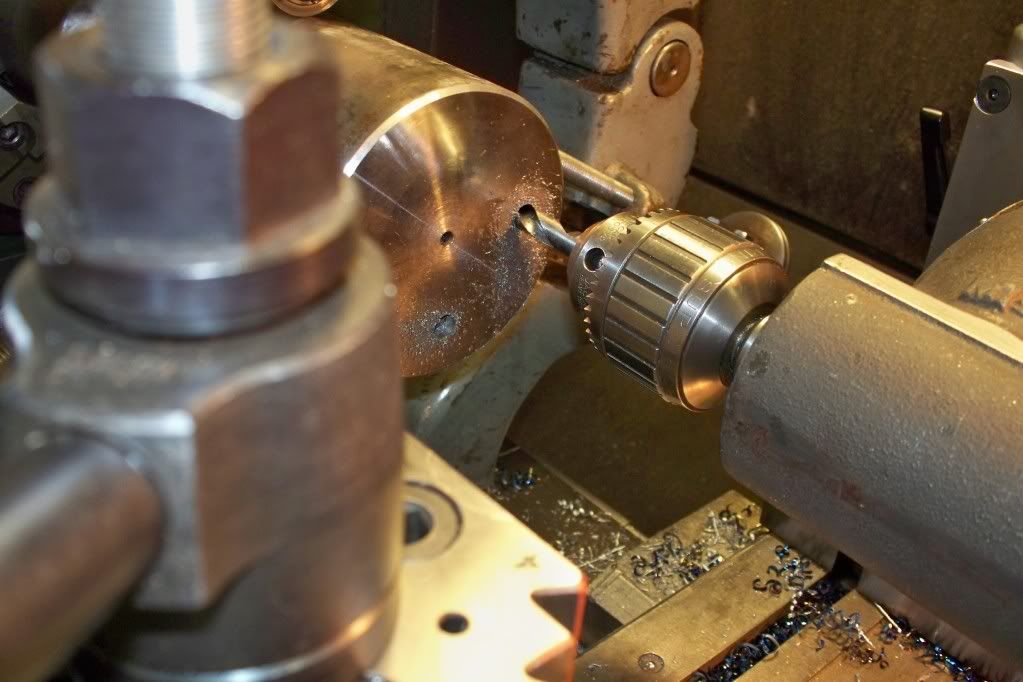
Some of you may remember the chicompos minimill I mounted on the cross slide of my American lathe. It worked good enough to do the jobs, but being underpowered and chinese got the best of me. So I figured I'd try to make my own. I used 2'' 1045 chrome bar mounted to a 3/4'' plate with a 2''x4'' block fastened to it. Bored out the holes and pressed in the bars. The bars are flatted for set screws and one bar is grooved for a rack gear.
ml1.jpg

ml2.jpg

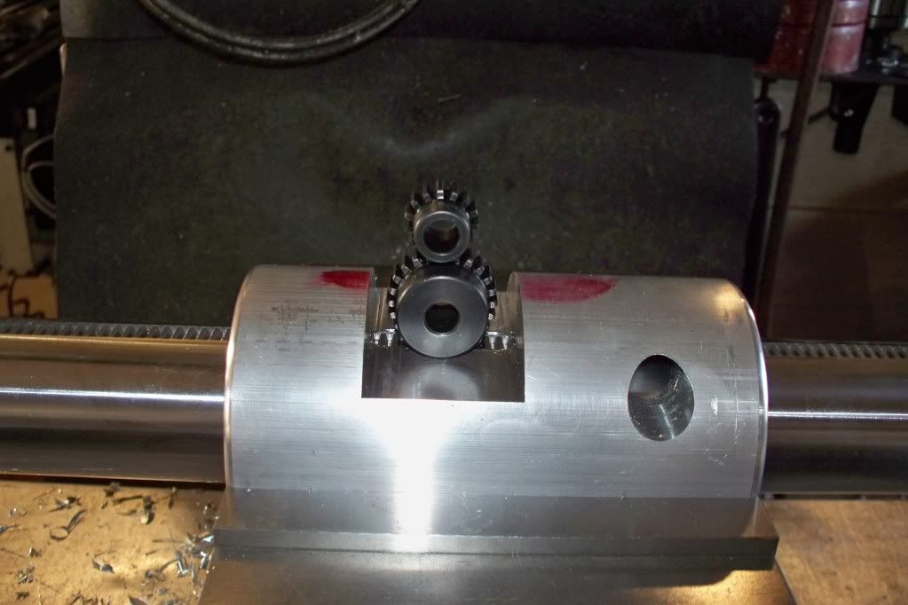
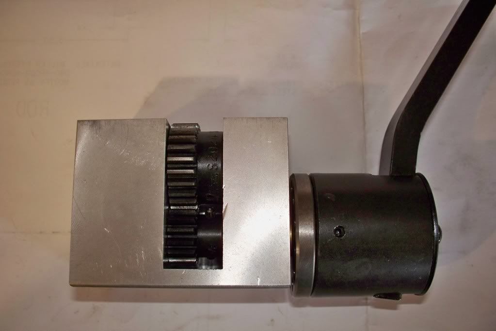
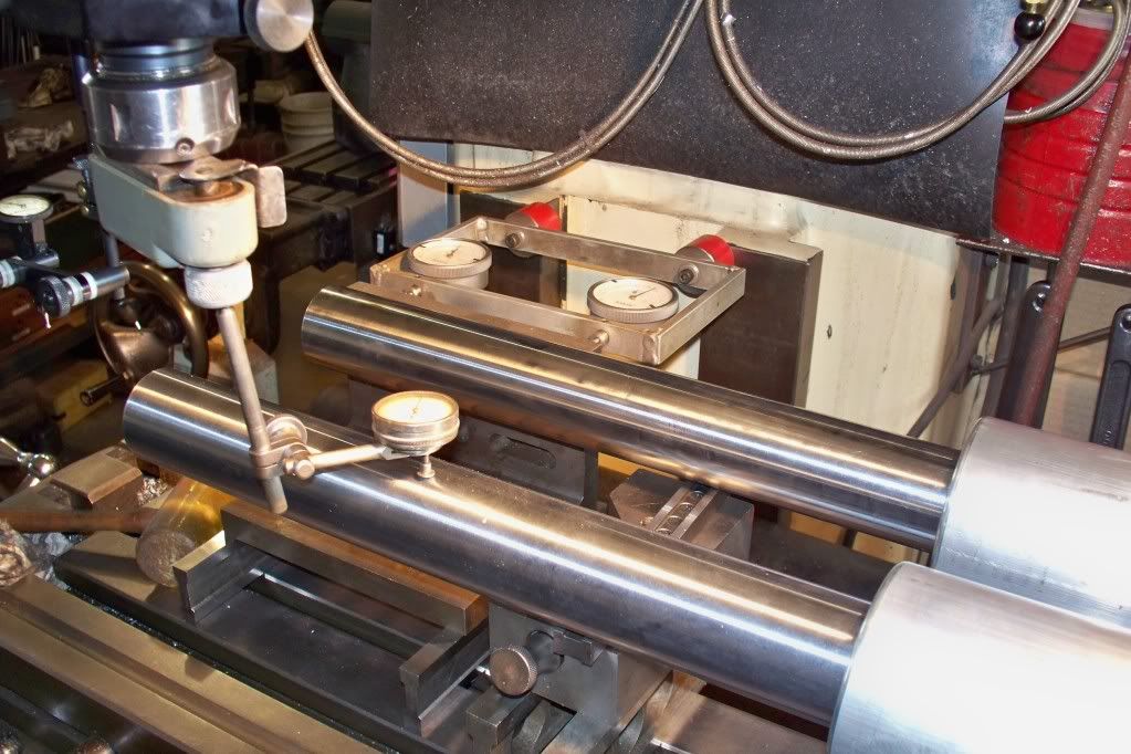
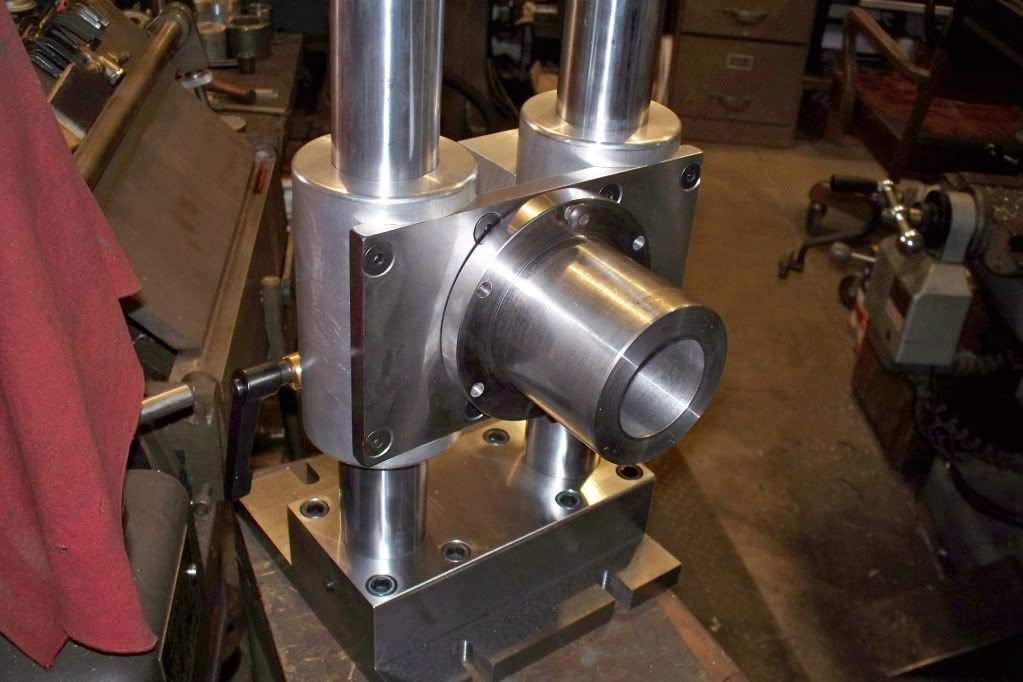
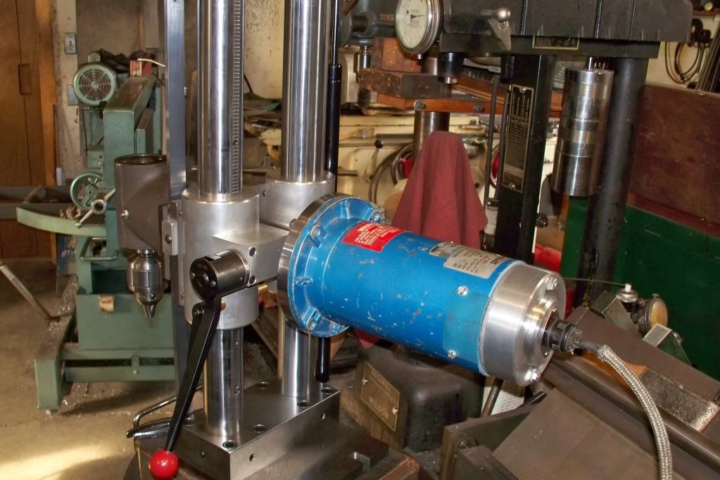
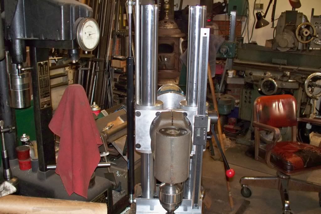
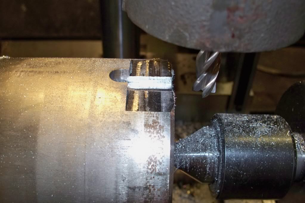
Next came the slide tubes. After boring, one needed to be cut out for the gear drive box. I used two gears for two reasons. One, so I could have the rack gear in the backside of the column. Two, so I could have a 2:1 ratio for ease of movement.
ml52.jpg

ml6.jpg

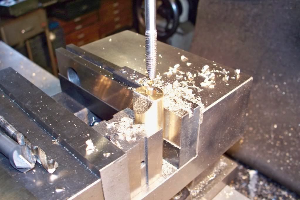
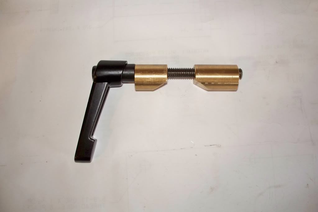
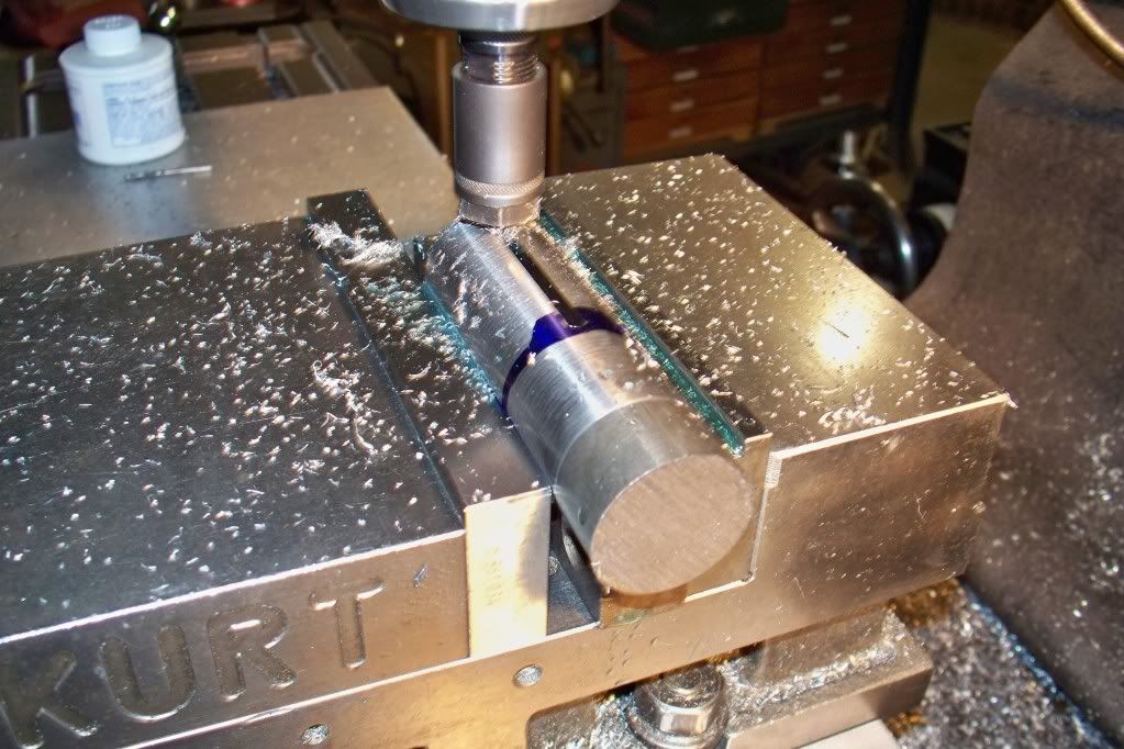
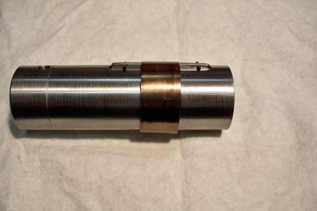
Now there needs to be a way to lock this thing in place, so I made some brass wedges for each slide tube.
ml3.jpg

ml42.jpg

More to come.
 
With those pieces assembled, I trued it up on the mill to cut flats on the slides to accept a mounting plate for the nose piece.
ml7.jpg

ml9.jpg

ml10.jpg

The mounting plate is attached, along with the nose piece. This will hold a Dorian right angle adapter for a Bridgeport.

ml11.jpg

Next comes the coupling to attach to the R8 drive of the angle head. I milled a 5/32'' slot in the coupling to hold the key. Had some kind of return spring in stock, so I wrapped a few rounds of it around the key(which is pinned to not fall through). This way, you just push the head on the nose and turn until it clicks, instead of trying to locate the key blindly.
ml12.jpg

ml13.jpg

More to come...if you can stand it!
 
I 'spose you noticed that I've been tapping with a drill chuck to hold the tap. Don't ever do that! OK, now we have to make a motor mount. First was the extention tube, then the flange to mount the motor to.

ml14.jpg


ml15.jpg


Here is the motor mounted to the flange. It's only a 1/3hp, but it's all I have at this time. I think it will work for a test putt. Second pic is the RA head on the nose.

ml16.jpg


ml17.jpg


Next episode: Test putt
 
Forgot to mention, I put a readout on the right side and a gas spring on the left to keep it from free falling. Here it is mounted to the lathe. Knowing I occasionally need a bolt pattern at the bar end, I felt this may work. This is important to me, because some of these bars are a few hundred pounds and to long for the mill, even when sitting on the floor clamped to the table.

ml18.jpg


Here I cut a wrench flat and then tried out a keyway. Damn thing works. Like I said though, a 1/3hp motor is on the skinny side of power, so I'll be looking for something bigger. Thanks
Ray
 
Ray, that's so cool it froze my ear wax. Nice design and nice execution.

I'm adapting a Sherline mill head for my Myford. These heads can be ordered with integral ER16 spindle noses (from their 'Industrial Catalog'), which greatly reduces tool overhang. Thanks for the inspiration.

Mark
 
Really beautiful work, Ray, as usual. What a tutorial as well as as an outstanding example of creative design and craftsmanship.

LL
 
Last edited:
Beautiful, useful, and cleaver tool! Excelent work! Looks to be a heavy duty attachment. I'm sure you will find uses beyond your initial reasons for the build. Thanks for the pics. and the idea. Next, a degree wheel behind the BP r.angle housing. Or not.
Krutch
 
Ray, that is a truely awesome peice of work. Excellent design and execution. Takes a lot of gumption to see a project like that thru from start to finish also. cheers and thanks for sharing it with us.:cheers:
 
So what's the purpose of this contraption? You do have a mill, right?

I can think of lots of things it would be very useful for...... because you already have the work in the lathe, you are already lined up with the axis, so there is some setup that doesn't need to be done.... and you have a linear movement already linked to the turning of the work.

With indexing added to the basic lathe, one can see cutting a pinion on the end of a shaft, splines, flats, keyways, etc.

Then there are things that look like the shaft of a yankee drill (very coarse "threads"), potentially thread milling, the list goes on and on.

Of course it might be ever so slightly impolite to point out that one of our fellow members makes and sells items which are pretty much like this... the "VersaMill".

But that is very nice work.....
 
Great to see someone making cool stuff.

I thought drill chucks were for holding taps? Done it a million times. The drill chuck doesn't know it's holding a tap.

JW
 
For the uninitiated, you should absolutely hold a tap in a drill chuck unless you want to spend lots of time cranking on a tap handle. It's called power tapping and like Ray has shown in his photo, use a key chuck and tighten it just enough to drive the tap. If it meets too much resistance, it just spins in the chuck. Don't use a keyless chuck for tapping however unless you're sure it won't bind. Keyless chucks are self tightening and will snap the tap off in your part if it meets any more resistance than it should.
 
To the O.P. I say good work, your project looks like it works great.

To the tap discussion, I add that the Jacob's Chuck is a very useful tool for power tapping, I use it myself all the time. If you are worried about breaking the tap, simply use the chuck to start the tap nice and square and get most of the threading done, then hand tap the last few threads.


Back
Top