What's new
What's new

What is the minor diameter of a thread in terms of its nominal diameter and pitch?

tlewis3348

Plastic
Joined
May 4, 2018
I'm trying to find the formula for calculating the tensile stress area of a bolt. According to page 1528 of The Machinery's Handbook (29th Ed.), that formula is given as A_S=(π/4)*((d_m+d_p)/2)^2 where the pitch diameter is d_p=d−0.649519×P, and the minor diameter is d_m=d−1.299038×P.

I was trying to understand where the definitions of d_p and d_m come from. The Wikipedia page for the Unified Thread Standard (link) was very helpful for understanding that. However, it is not clear where the equation for d_m comes from. The value 1.299038 is equivalent to 3*sqrt(3)/4. Translating this to be in terms of H instead of P results in d_m=d−2*(3/4)*H. In other words, it would appear that the boxed dimension in the drawing below (versions of which appear on pages 1807, 1912, and 1973 of the handbook mentioned above) should be .75*H instead of .625*H.
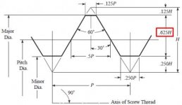
Basic Profile of Screw Thread.jpg

I'm assuming I must be missing something obvious here because I'm seeing variations of the formula for A_S listed above everywhere. The best I can figure is that the equation for A_S assumes that the outermost 1/8th of the thread's V is included in the nominal diameter of the bolt. However, I can't find any justification for this. If someone could explain it to me, I would greatly appreciate it.
 
tlewis3348 --

You're essentially asking about the difference between 1) the Sellers (aka Franklin Institute, US Standard, and American National) threadform, and 2) the Unified (aka ISO Inch) threadform.

In their most basic flavors, both the Sellers and Unified threadforms have 60 degree flank-to-flank angles and and a 1/8 x Pitch flat at their Major Diameters. They also have flats at their Minor Diameters, 1/8 x Pitch for the Sellers threadform, and 1/4 x Pitch for the Unified.

This means that the measured-along-flank length of a single thread of 1) a Sellers-form screwthread is (1 - 1/8 - 1/8) x Pitch, which reduces to 3/4 x Pitch, and 2) (1 - 1/8 - 1/4) x Pitch, which reduces to 5/8 x Pitch for a Unified-form screwthread.

The Single Height (aka Single Depth) of a screwthread is measured radially, and is thus shorter than the along-flank length; the Single Height of a Sellers threadform is 3/4 x Pitch x Cosine 30 degree . . . and as you might guess, the Single Height of a Unified threadform is 5/8 x Pitch x Cosine 30 degree.

Incidentally (Mk I): H is the Single Depth of a 60-degree Sharp V thread, and is derived as Pitch x Cosine 30 degree.

Incidentally (Mk II): The basic geometry of the ISO Metric form screwthread is exactly that of the Unified.

John
 
If you are lazy, you can also get that data from Machinery's Handbook or other places with thread charts. If you look at a page of, say, 1-4x20 external thread, the minor diameter is listed as .1876 in my book.

Tom
 
You don't really have to get down to the fine points of different thread standards (US vs. ISO or whatever). The basic drawing that you show is enough. But you have to know how the threads are specified. The real thing that determines a thread's diameter is the PITCH DIAMETER. It may not say this in the Handbook or any other standard, but it really is the most basic number for any particular thread. The flat at the crest and the fill at the root are both somewhat subject to variation. Of course, there is a tolerance range for the Pitch Diameter also, but it is still the basic number.

Checking a little math against a particular thread listed in Table 3 in the Handbook tells you that the the Pitch Diameter is calculated from the (nominal?) value of the Major Diameter by assuming that the flat at the crest is exactly 1/8 (12.5%) of the Height of a sharp Vee thread. This 1/8 of the Height is NOT included in the calculation so the Major Diameter of the thread is at that flat, not at the sharp Vee point.

For instance, using a 1-8 TPI thread, the Height of a sharp Vee thread is 1/8" x cos(30) = 0.1083". Then the Pitch Diameter can be calculated as MD - 2 (3/8 H) = 0.9186". This value is exactly what is shown in the Handbook for the maximum PD for that thread. My point is, the 1/8 flat at the crest is NOT part of the thread nor is it to be included in any calculations.

A similar calculation gives the MAXIMUM Minor Diameter as MD - 2 (5/8 H) = 0.8626". Now things get a bit more fuzzy. Why is that? Well, that is the Maximum Minor Diameter, but if a thread is being cut in a production situation, the cutting tool will wear. So it is anticipated that the tool will start cutting the thread deeper than that. In fact, the UNSTATED assumption is that the thread cutting tool will start cutting the root of the thread at the same 1/8 H point from the sharp Vee as the crest is specified at. How do I know this? I have no written references, but I have done a lot of checking and it is what makes sense. In fact, it is the ONLY thing that makes sense when both tool wear and the history of thread forms are taken into account. Anyway, the Minor Diameter is a very poorly controlled number in a thread form. It is, in fact the one that varies the most and you can not count on anything except the maximum value given in the Handbook. This is why I said that you do not have to sweat the fine points.

But that maximum value is not what you want for a strength calculation: you want the MINIMUM value, not the maximum one. And this is where any/all of the published formulae will not serve. You need to go to that 1/8 H value that I have stated is the real starting point for a threading tool. I can not guarantee this number, but, as I said, it is the only one that makes sense when you consider all the factors. So, foo a safe calculation of the tensile strength of a bolt you should use this formula:

Minimum Minor Diameter = MD - 2 (3/4 H). And for my 1-8 example that would come to 0.8356".

When I was talking about wear on the threading tools, that would apply to both a thread cutting tool and a thread rolling tool. Both will wear in use. I used the Class 1 values for the 1-8 thread in my example calculations. And I only calculated the maximum value of the Pitch Diameter. The minimum value for the Pitch Diameter does not follow from the minimum value of the Major Diameter: The Pitch Diameter appears to have a smaller allowed range. To be completely safe you may want to subtract twice the value of that PD range in your calculations of the Minor Diameter. Of course, these values do vary with the class of the thread.
 
But that maximum value is not what you want for a strength calculation: you want the MINIMUM value, not the maximum one. And this is where any/all of the published formulae will not serve. You need to go to that 1/8 H value that I have stated is the real starting point for a threading tool.

I had not thought of that. However, looking at some more detailed drawings, it looks like the bottom of the thread root is defined to be no less than H/6 and no more than H/4 from the bottom of the V (see drawing below).

25365d1281841478-thread-problems-metric-thread-profile.gif

Therefore, it would seem that the minimum minor diameter would be given as D_min = D - 2 * (5/8 + 1/4 - 1/6) * H = D - 2 * 17/24 * H. For your example of a 1-8 TPI thread, that would give a (minimum) minor diameter of D_min = 1" - 2 * 17/24 * 0.1083" = 0.8466". Clearly, in most cases, the difference (between that result and the 0.8356" value that is calculated using D_min = D - 2 * 3/4 * H) would be negligible. Furthermore, obviously there must be some way of getting D_min = D - 2 * 3/4 * H because that's clearly what is being used in the formulas for A_S that I'm trying to understand. I just want to make sure I have a correct and thorough understanding of where these numbers are coming from, and I'm not sure I'm there yet.
 
You're essentially asking about the difference between 1) the Sellers (aka Franklin Institute, US Standard, and American National) threadform, and 2) the Unified (aka ISO Inch) threadform.

That would only be true if the equation for A_S given on page 1528 of The Machinery's Handbook (29th Ed.) was derived for the Sellers threadform and did not apply to the Unified threadform. However, from what I understand, the only difference in the two is the tolerances used. Furthermore, because the Sellers threadform is not really used anymore, my suspicion is that if there would have been any difference, the handbook would have used the more commonly used threadform for the derivation.
 
If you are lazy, you can also get that data from Machinery's Handbook or other places with thread charts. If you look at a page of, say, 1-4x20 external thread, the minor diameter is listed as .1876 in my book.

Yes, but I want to know where these numbers are coming from because the earlier you use rounded numbers (like 0.1876), the more rounding errors are introduced into your calculations. Although these rounded numbers are fine for use in manufacturing and some calculations, it is normally better to use the exact value.
 
What is the actual question you want to know the answer to?

The only way I can see to derive the equation for A_S given on page 1528 of The Machinery's Handbook (29th Ed.) is to use a minor diameter of D_min = D - 2 * 3/4 * H (where D is the nominal diameter and H is the height of the pitch). However, the way I see D_min described in most places (both in the handbook and around the web), it is given as D_min = D - 2 * 5/8 * H, which is clearly different than the value apparently used in the formula for A_S. My question is, what is the reason for this apparent difference?

EPAIII suggested that the formula might be accounting for the fact that the minor diameter defined by D_min = D - 2 * 5/8 * H is actually the maximum value for the minor diameter and it would be better to use the minimum value to calculate A_S. However, in my response, I pointed out that it appears that the minimum minor diameter is defined to be D_min = D - 2 * 17/24 * H, which is still H/12 more than the value apparently used in the formula for A_S. So the question then is, what is the reason for this difference?
 
tlewis3348 --

Get your calculator and run this calculation: 2 x (3/4) x Cosine 30 Degree.

That 1.299+ value you ask about is a "magic number" that was based on the fundamental geometry of the Sellers threadform, which William Sellers suggested for a US standard in 1864 (IIRC). Yes, the Sellers threadform has officially obsolescent since 1949 (again, IIRC).

Beyond that, there is a significant difference between the Sellers and Unified threadforms: the Flat at the Minor Diameter. The Minor Diameter Flat of a Sellers threadform is 1/8 x Pitch, that of a Unified threadform is 1/4 x Pitch.

John

Ah! Thanks for that explanation! So basically, what you're saying is that the formula used to calculate the stressed area in a threaded bolt is outdated and, by extension, so are all the tables of values showing clamping load or prescribed torque values. Am I understanding that correctly?
 
Over the years, I've found many, many textbooks and other "references" (not just documents) contain data that were outdated decades before their publishing-or-manufacturing dates. There's no doubt in my mind that the vast majority of these errors are out of simple ignorance . . . the authors, editors, and manufacturing people generally aren't, and can't reasonably expected to be, technical authorities.

I've never seen an inch-graduated "fishtail" center gage that correctly lists Double Depth of Screwthread data for the Unified threadform. Most tabulate Sellers-form double-depths, but some actually tabulate Double Depths for the Sharp-V threadform that has been flat-out obsolete for well over a century.

Wow! Okay. Good to know. Thanks!
 
The op is looking for the tensile stress area of a bolt.
I dug up my Engineers bible. That would be the fourth edition of Mechanical Engineering Design by Joseph Shigley.

On pge 359 He writes: "A great many tensile tests of threaded rods have shown that an unthreaded rod having a diameter equal to the mean of the pitch and minor diameters will have the same tensile strength as the threaded rod. The area of this unthreaded rod is called the Tensile-stress area A(subscript t) of the threaded rod; values of Asub t are listed in both tables."

There you go. its the mean of pitch and minor diameters and the relationship of that number to strength is empirical.

I think you misunderstood my question. My question isn't how to determine the tensile stress area (I actually included the formula you described in my original post), but rather how to find the minor diameter used in that equation. Looking it up in a table is one option, but that introduces sometimes significant rounding errors. I would much rather calculate the minor diameter directly. Furthermore, this gives me a much more fundamental understanding of where the numbers come from.
 
Buy you a copy of the standard put out by ASME/ANSI B1.1 Screw Thread Standards for Unified Threads. You'll have to do some reading and looking, the formulas are there for calculating the minor diameters for external and Major diameters for internal threads in design. The formulas are too detailed to put on here. I use them quite often and have it along with others I use with threads in a spread sheet that I've used for the last 25 years.

Ken
 
I don't know where your drawing came from but I was working from the drawings on page 1713 in Machinery's Handbook, 26th Edition. These drawings, near the front of the section on threads, did not show any spec. at the rounded root of the external thread, only the fact that the root may be rounded below the 0.25H point. But I looked further and on page 1751 I found a drawing that showed both internal and external, Unified Screw Threads and it has a lot more information. One of the items it shows is that the Minimum Minor Diameter of an external thread is at the point where the distance between the thread flanks is 0.125P. This is exactly what I was describing as the 1/8H or 12.5% point. So you are apparently allowed to go that deep in cutting or forming an external thread.

This seems to make a lot of sense as the crest of an internal thread, which has to fit in the root of the external ones, is allowed to extend to the 1/4H or 25% point. That drawing on page 1751 answers a lot of questions. It brings all the elements of both internal and external threads into clear focus.

My numbers seem to stand.

I did not reproduce that drawing here as it is likely protected by copyright.


I had not thought of that. However, looking at some more detailed drawings, it looks like the bottom of the thread root is defined to be no less than H/6 and no more than H/4 from the bottom of the V (see drawing below).

View attachment 227777

Therefore, it would seem that the minimum minor diameter would be given as D_min = D - 2 * (5/8 + 1/4 - 1/6) * H = D - 2 * 17/24 * H. For your example of a 1-8 TPI thread, that would give a (minimum) minor diameter of D_min = 1" - 2 * 17/24 * 0.1083" = 0.8466". Clearly, in most cases, the difference (between that result and the 0.8356" value that is calculated using D_min = D - 2 * 3/4 * H) would be negligible. Furthermore, obviously there must be some way of getting D_min = D - 2 * 3/4 * H because that's clearly what is being used in the formulas for A_S that I'm trying to understand. I just want to make sure I have a correct and thorough understanding of where these numbers are coming from, and I'm not sure I'm there yet.
 
I don't know where your drawing came from but I was working from the drawings on page 1713 in Machinery's Handbook, 26th Edition. These drawings, near the front of the section on threads, did not show any spec. at the rounded root of the external thread, only the fact that the root may be rounded below the 0.25H point. But I looked further and on page 1751 I found a drawing that showed both internal and external, Unified Screw Threads and it has a lot more information. One of the items it shows is that the Minimum Minor Diameter of an external thread is at the point where the distance between the thread flanks is 0.125P. This is exactly what I was describing as the 1/8H or 12.5% point. So you are apparently allowed to go that deep in cutting or forming an external thread.

This seems to make a lot of sense as the crest of an internal thread, which has to fit in the root of the external ones, is allowed to extend to the 1/4H or 25% point. That drawing on page 1751 answers a lot of questions. It brings all the elements of both internal and external threads into clear focus.

My numbers seem to stand.

I did not reproduce that drawing here as it is likely protected by copyright.

I think I found the drawing you're referring to. That helps a lot. Thanks!


Back
Top