What's new
What's new

Monarch Series 61, Rebuilding for Improvement

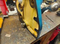
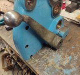
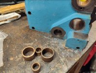
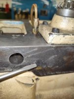
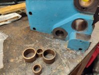
I got the leadscrew end bracket cleaned up, and the bearings for feed rod and clutch rod shoved out:

26.jpg

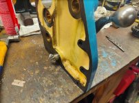
Painted, and I'll be drill oil passages and adding gits oilers to 3 of the 4 bearing holes. Exception is the leadscrew reverse. That slides in and out, besides rotating, so easy enough to lube.

27.jpg

QCGB off:

28.jpg

End cover removed. Replacing seal will be easier with shaft out of the way too. After seeing bushing and shaft for feed rod, I'll be adding a gits oiler for that too.
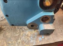
29.jpg

The problem bushing, is wore, but so is the shaft. I'll be cutting that down, and/or replacing with Mike Thomas's magical parts supply warehouse :D. About .020" wear on the shaft, also taper pin hole is egged out a bit. I'll be going up a size and reaming that out, if I reuse.
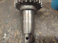
30.jpg
 
I discovered a problem with the bevel gears in qcgb, for the clutch lever mechanism. But I have a fairly easy solution.

First, I had an "oh sh@%" moment when I removed qcgb end plate. I looked down and saw bevel gears. And I didn't time them, or mark shafts prior to pulling end cover. . .

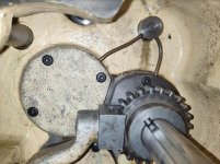
You can see the one bevel gear on end plate:

38.jpg

The other bevel gear in qcgb:

39.jpg

Why does it matter ? The bevel gear on end plate is pinned to clutch arm, and I need it to operate at a fairly specific location.

The bevel gear in qcgb is keyed internal for a shaft, that shaft also keyed to work linkage to head stock, and needs to operate in a certain range. . .

Well a funny thing, this turned out to be the least of my problems. :D

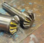
I had 3 teeth on one gear, and 4 on the other with terrible wear:

34.jpg 44.jpg

Good news though. Simple solution and I don't even really need to replace them. These gears never spin 360 degrees. They only operate on 30 to 45 degree, back and forth rotation. That's why only 3 or 4 teeth are wore, its always on those same teeth.

The answer is to relocate them 180 degrees from their original mating. All the other teeth are brand new and have never been used:

45.jpg

I'll explain why 180 degrees further, and what I have to do to get timing right. . .
 
Continued from last post. . .

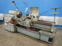
If we look at the lathe it has two clutch arms. One at qcgb, one at apron. You want both at a comfortable operating range, but you'll also bang into to something if you have the timing off:

42.jpg

The clutch operating lever at qcgb is directly drilled through and pinned to the one bevel gear. So the one reason to rotate 180 degrees, it allows me to use that same drilled hole. Albeit, I will need to run a taper pin reamer to get holes to match, and most likely the next size up.

So 180 degrees for unused teeth, plus I don't need to re-drill a hole. And good news, they hit the shaft dead center when drilled, spining 180 the holes line up nice:

46.jpg

Now the bevel gear inside qcgb, also will turn 180 degrees. Its keyed, and turns a shaft:

40.jpg

When assembled, that shaft passes through bed to rear side of lathe:

41.jpg

That shaft having key slots on both ends. On the rear side of lathe it connects to a lever and linkage which connects to headstock:

43.jpg

My intention is to cut a key slot 180 degrees from the original slot on rear side of lathe. That will allow original operation of clutch: Push to engage, lift up to disenage.

I could allow lever to stay original to shaft, just flipped opposite side. But that would reverse operation of clutch: lift to engage, push down to disengage.
 
Last edited:
I split the two housings from left end of qcgb:

32.jpg

That allowed me access to a chamber in the left end of qcgb. I was able to clean the mung out of the bottom and get clean oil shot into the bearings:

47.jpg

While I hate just exploring, and taking the time to remove parts sometimes, I'm usually glad after the fact. In this case I pulled an oil junction that was pressed into the bore, and oil fed from above. Getting it moved back I found what I guess is a 65 year old felt. :D

48.jpg

Cleaned that out and jammed new felt in:

49.jpg
 
Checking some of the bearings. Timkins, and in good shape:

51.jpg

Got mung and grit cleared out in the space between opposing bearings:

50.jpg

Finally on to the main reason I pulled qcgb, the stub shaft for feed rod:

30.jpg

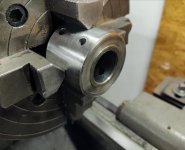
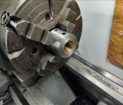
Got it set up and cut down true. Also cut down the end step where feed rod coupling connects, the coupling was a little loose as well. I'll bore the coupling and add a sleeve to tighten it up:

52.jpg
 
I had finished cutting the stub shaft which connects to feed rod, by way of a coupling. I had also cut the lower step which mates to coupling as the connection had wobbled around a bit.

53.jpg

So on the coupling itself, I want to face it off, plus bore it to add an internal sleeve, to fit that stub shaft. Here I'm setting up to bore:

54.jpg

Once bore was done and I had measurement, I used some brass stock to to make the internal sleeve. Here I'm using a power fed tail stock. A real pleasure to use for such things. I hate to give it up, but I'm not sure I can keep 3 lathes :D. We'll see, I have to think about it. Anyway that tail stock is a beast operating at a low low reduction I can push through pretty much anything:

55.jpg

I got the sleeve parted off and pressed into coupling. Got it bored to fit stub shaft. I left a small step on the face, its just under the diameter of the bearing portion of stub shaft:

56.jpg

The taper pin hole was at #5, but kind of egged. Reaming it I was getting to end of a #5 reamer, so had to go up to a #6. But I kept diameter as small as possible, and ordered longer #6 taper pins to use the skinny end.:

57.jpg
 
I don't want to come off as criticizing your work as its going really well and I'm enjoying it for sure, but just wanted to say that I think you will be a lot happier with bronze sleeves rather than brass, over the long haul.
 
I don't want to come off as criticizing your work as its going really well and I'm enjoying it for sure, but just wanted to say that I think you will be a lot happier with bronze sleeves rather than brass, over the long haul.

On all my bearings, or bearing sleeves I use c932 bronze.

This particular bore the shaft dont spin inside coupling. It has a taper pin hammered through shaft, brass sleeve and collar.

I don't particularly make a habit of using that material though, it was just a piece of stock that happened to be close in size.

The main reason for this repair was basically both end bearings for feed rod were whipped. With repairs and bearings replaced,this coupling should run true without wobbling around.

The only other bad news is that I need to repair feed rod connection through apron as well. But I know that already, and have been prepping some for that too.
 
A mystery !! Part 1.

Sometimes it feels like being an archeologist working on old machines. Going back in time to see what others did, be it the manufacture or someone else. :D

In this case, working on the qcgb. I showed the stub shaft repair for feed rod. Moving on to the qcgb end plate to replace bearings for that stub shaft, plus bearings for the clutch bevel gears. I got the bearings pressed out:

58.jpg

Wiping the bores clean, I found what felt and looked like an oil feed hole for the feed rod bushings, at the top of bore:

59.jpg

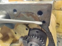
Now the interesting part. . . directly above that hole is a bore for another bushing. And no hole is drilled through the bushing :eek: ! More interesting yet, note the paint on bushing ! My guess is factory paint. But I suppose not impossible someone replaced bearing and painted the interior.
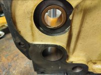
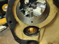
I bet the whole reason I needed to make this repair is the oil holes were not drilled in the bushings.

60.jpg

As we continue up the line to directly above that bushing, we have the bore for main lead screw. It does have an adjoining oil hole to that lower bearing, which is not drilled:

61.jpg

One thing bothering me. . .and part of the mystery. How does oil get to the upper bearing for main lead screw ?

I discovered something about the enclosed qcgb. It has a site glass for oil level. Guess what ? When full the oil level is below any gear in main gear cluster at center chamber of qcgb. One gear in far left chamber will touch into the oil level. This means the gears in main chamber are not going to catch and throw the oil all over the inside of gear box. And the end plate I'm working on is the far right side.

The qcgb site glass, and oil level are mostly for its own oil pump. And the oil pump feeds the Timken bearings for the main shafts inside the qcgb.

So. . .how is oil supposed to get to the far right end plate for these bushings, and all the way up to the main lead screw bearing ?

To be continued. . .
 
The mystery, part 2.

Examining the right end cover more closely, I see a plug hammered into the top of end plate. During manufacture they must have used a long drill bit to punch down through the three bearing bores:

63.jpg

This still does not answer how oil gets up here.

But continuing to examine end plate I find another plug for a cross drilled passage:

64.jpg

Now we're getting somewhere. That cross drilled passage hits the downward passage. And looking at the gasket surface of end plate, I have an open oil hole:

65.jpg

Going over to the qcgb itself, looking to where the oil hole goes on main housing:

66.jpg

To be continued. . .
 
The mystery, part 3.

Following the passage down main casting, I find another plug for a cross-drilled, and intersecting passage.

And look at that, a copper oil line screwed into the housing:

67.jpg

Previously I thought that oil line only fed the Timken bearings on this side of qcgb, as that oil line is directly above this two branch tree:

68.jpg

Well mystery partially solved anyway. The end plate does get oil fed to it, and we see how. Its just unknown to me if the bearings were replaced and no oil holes drilled in them, or an oversite during manufacture.

58.jpg
 
Getting set up to make the bearings for feed rod stub shaft in qcgb. 1.75" c932 bronze hollow round:

69.jpg

Bearings made for feed rod stub shaft, and clutch bevel gear shaft, all pressed in. New seal for the clutch bevel gear shaft.

Bearings for the feed rod stub shaft, I cut 4 length wise minor oil channels. The outer bearing I have a wider flange type end to help with end thrust from feed rod coupling.

I also drilled and made sure passages for oil, from oil pump are now open. Further insurance, I drilled and added a gits oiler where I can pre-lube before start up.

70.jpg

The oil seal is the same for rear side of qcgb as well as at the clutch lever, a cr7513:

71.jpg

The shafts are in, and hammer pins knocked in clutch lever and feed rod coupling. I do have the clutch bevel gear 180 degrees out from original position as I discussed in an earlier post.

Both shafts feel perfect now. They spin nice and no banging around. Oil clearance around .001-.0015". I have end thrust on feed rod stub shaft at about .0015"-.002".

72.jpg
 
A guy that works on worn bushing and worn drivelines on boats sees what could be better in design. The shaft needed cleaned up and a new bushing made. Cutting a couple oil retention groves and drilling for a Git's oiler isn't that much added labor to the job too improve what's there. It's an improvement
I Understand the reasoning behind making it better.

Could just pop in a bushing and it may never wear out in a lifetime.
I can see some seeing it as overdone but I do the same type of repairs while I'm there. Slop in that shaft wears on the half nuts.

It's a privilege of the machine owner to be a little anal.:rolleyes5: .
Bushings and shafts are most of my lathe use right now. Often neglected of regular oiling for years.
This lathe has to outlive the current owner and still be good for that daughter to make parts that's getting the bug. She measures in tenths.

I did product change setups on production machinery for years. You have too live with and make adjustments for Slop in worn parts daily. It adds work and hurts production in the long run. I always wanted to make it right but had to fight with the slop.
A lot of rebuilds on the Monarch forum have improvements to the original design. Monarch built a great lathe but they wear
As a long time machine mechanic owning a Machine tool is like dying and going to heaven. You appreciate owning it and what you can do with it . You buy worn machinery and rebuild for improvement.

Documenting these repairs helps the people that google with problems. Like the shifting fork repair
 
Believe me, sometimes I really wonder what I'm doing :D. I often just want to be done. Having gone through the time and pain involved, once finished, I feel its really worth it.

I've got some machines I've gone through, and it took a stupid amount of time. Once past all that though, I can just go hit the power button and they do what I want, and look half way decent too.

Still have a long way to go on this one, but I feel like I can see the end, or completion. So I'm alright with it. I've had a pretty productive year, year and a half. Hopefully finish this in the next few months.


Ill buy a machine and tell myself that I'm not going to get in too deep. That doesn't always work as you see problems that need repair. Do it right or do it twice.

I had an exposed bushing like that in a really dirty place. Too keep grit out I put a oil seal with the face against outside of the casting {cup out} I silicone sealed it and pined it on with tag screws. Sort of an exterior shield.
You should be able too keep any grit flushed out now with oil now with the Gits oiler.

Monarch really thought out all those oil passages. There is one that oils the half nuts on the 10ee that gets clogged easy. You will be working on that 10ee next. It never really ends.
 
I had an exposed bushing like that in a really dirty place. Too keep grit out I put a oil seal with the face against outside of the casting {cup out} I silicone sealed it and pined it on with tag screws. Sort of an exterior shield.
You should be able too keep any grit flushed out now with oil now with the Gits oiler.

\

I really like the seal idea to keep dirt/debris out. On the feed rod stub shaft though, I wanted to control end thrust, because the feed rod coupling had previously contacted the end plate and wore into it.

I forgot to mention it, but what I did on thrust face was grind two oil reliefs, at 3 and 9 oclock. So dirt falling down won't fall directly into it.

Also I ground oil reliefs wider toward ID of bushing, and taper to almost nothing as it gets to outer edge. In that way I'm hoping not to collect debris. I re-posted the pic and circled in red as its not highly visible:

73.jpg
 
I really like the seal idea to keep dirt/debris out. On the feed rod stub shaft though, I wanted to control end thrust, because the feed rod coupling had previously contacted the end plate and wore into it.

I forgot to mention it, but what I did on thrust face was grind two oil reliefs, at 3 and 9 oclock. So dirt falling down won't fall directly into it.

Also I ground oil reliefs wider toward ID of bushing, and taper to almost nothing as it gets to outer edge. In that way I'm hoping not to collect debris. I re-posted the pic and circled in red as its not highly visible:

View attachment 330753

It sounds like you have already thought about keeping the crud away.
Are you controlling the end thrust with bronze washers on both sides and setting the feed rod coupler to set it ?
I didn't think there was room for a seal anyway.

I forgot to mention that you can shave the flange off the seal so all you have is a flat round with the rubber cup. That looks better if its visible and the cup doesn't collect crud. Less protection for the rubber cup and spring though.
Bringing a machine back up to snuff is time consuming. A friend said I don't have your patients. I really don't have that much patients. Right now I'm getting going overboard painting the 10ee. I just cant keep myself from going overboard. Which defects do you not fix.
Shiny Paint does nothing accept satisfies the owner. I want it done!
Painting weather is slipping away.


Is the QCGB ready for reassembly. ?
 
Are you controlling the end thrust with bronze washers on both sides and setting the feed rod coupler to set it ?


Is the QCGB ready for reassembly. ?

I didn't add anything to control thust from the other side. Though I suppose I could have. Wear from that direction was minimal though. My theory is apron is working when moving toward chuck, so probabaly more drag on feed rod that direction. Verse unloaded when moving away from chuck. You can see just light markings here, though not a great pic, the hole just past bevel gear:

38.jpg

I did get qcgb back together. Also got bevel gears and clutch lever oriented:

74.jpg

I'm going to set qcgb back on base, but I wont bolt it up till lead screw is in. Leadscrew bearing flange is a trick and a half on a 16". I need to float apron, lead screw, and qcgb in at the same time. Due to bed way blocking bearing flange. A pic from initial tear down:

53.jpg


Back
Top