What's new
What's new

Replacing a servo driver

Did you turn the number screw to ?6? on initial power up, then move it to the number required by the controller? On a Mazak w Mitsu drives, that initialization process is required every time you change a drive. I would find the manual or call Mitsu, they are awesome and support their products.

That procedure does not apply to the drive model the OP has.
 
The wire from the encoder to the drive had several contacts with good continuity straight through, and several that didn't seem to be connected. I pulled the encoder off and am trying to troubleshoot, is there a standard pin out for what should be ground and common, and which should be the outputs?
 
The wire from the encoder to the drive had several contacts with good continuity straight through, and several that didn't seem to be connected. I pulled the encoder off and am trying to troubleshoot, is there a standard pin out for what should be ground and common, and which should be the outputs?
What is the encoder part number?
 
The servo is a Mitsubishi HC-SFS102, the encoder doesn't have a part number (at least in English).
 
I couldn't find the manual for the servo, where are you finding that? Is it in the drive manual?
 
Yea in the drive manual. Posted a link earlier in the thread if you don't have it already.

I have the drive manual, just didn't occur to me that it would have the info, though it retrospect of course it would.

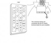
So, hook ground to N and 5VDC to S and then checking A through D for voltage while rotating the shaft?
 
I have the drive manual, just didn't occur to me that it would have the info, though it retrospect of course it would.

So, hook ground to N and 5VDC to S and then checking A through D for voltage while rotating the shaft?

I'd recommend taking some voltage readings at the cable end to verify as I'm not at my computer to look.

I can see pin S as positive voltage connected to P5 at the amplifier. I see LG (control common or "ground") connected to pin R. Pin N is the cable shield and shouldn't be used a ground return. I believe your encoder channels will be on pins C and D
 
......So, hook ground to N and 5VDC to S and then checking A through D for voltage while rotating the shaft?

Not sure what you would see when trying to check voltage. That style of Mitsu encoder sends data in a serial format rather than pulses like a differential encoder. Almost certainly a proprietary format. If you had an oscilloscope you might be able to capture data stream info but I don't know how you would ever figure out if it was good or not. Swap to a known good encoder.
 
Well there you go. Learned something new today.

Tangent: Do you know why they use this serial protocol over standard A/B or differential signaling? You mentioned proprietary so just to lock the user into buying parts from the OEM?


Back
Top