Isak Andersson
Aluminum
- Joined
- Nov 3, 2021
Hi folks.
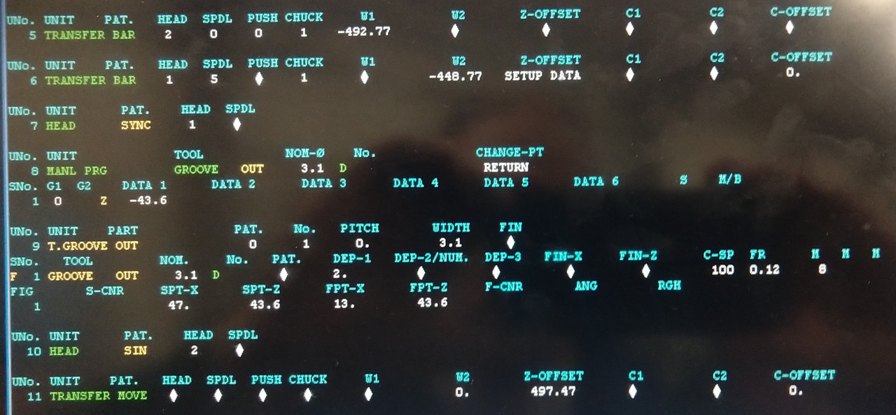
How can I part off with the part being held by both the main and the sub-spindle? Is there some way to do this in Mazatrol or do I need to make a manual program?
As for the sub-spindle bar pull, I assume I use transfer bar. The question is, is it best practice to put this at the end or the begging of the program? How would you do it?
Thanks!