What's new
What's new

How to Remove the Reverse Idler Stub Shaft in a 10EE?

Hobby Racer

Aluminum
Joined
Apr 18, 2015
I am trying to completely disassemble the headstock on my 1942 Monarch 10EE and I am a bit stumped on how to remove the reverse idler gear stub shaft. Its the small hollow stub shaft that the clutch rack shaft slides into.

Here is a picture from the top.
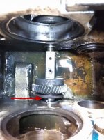
IMG_20220327_181614304.jpg


Here it is from the back. There is plug that appears to be pressed in where the shaft goes.
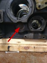
IMG_20220327_181605641.jpg
 
I am trying to completely disassemble the headstock on my 1942 Monarch 10EE and I am a bit stumped on how to remove the reverse idler gear stub shaft. Its the small hollow stub shaft that the clutch rack shaft slides into.
...
Here it is from the back. There is plug that appears to be pressed in where the shaft goes.
View attachment 345676
Get some fine sandpaper or steel wool and polish up the "plug". What you should find is that there is a smaller plug (EE-1095) pressed into the end of the stub shaft (EE-1673 ?), blocking the ID of the hollow shaft, and making it look like one big plug. If you lightly tap the center of the plug, the joint between the two parts should be revealed.

346150d1446414634-10ee-spindle-questions-clutch-gear-shifter-monarch_ee_99_headstock-idler-shifter-shaft.jpg


You can try prying against the shifter fork (EE-1101) and see if that will cause the shaft to move. If not, you need to tap a couple of holes in the shaft and use a slide hammer to pull it out. This would have been a lot easier if they had used a threaded plug in place of EE-1095

Cal
 
Last edited:
That is not a very good design from a serviceability standpoint! I think I'll try working around it first.
 
Ok, couldn't get around it so I had to take it out. As Cal said, drill and tap it, then a few taps with a slide hammer and it's out.

I think I will put in a threaded plug to make it easier for the next owner to rebuild in 30 years. :D

IMG_20220331_162403301.jpg IMG_20220331_162736958.jpg
 
What size tap did you use and what's the ID of the stub shaft?

Cal

I used a 3/8 fine thread for no other reason than that is what my slide hammer was setup for after pulling the reverse shaft (EE-1677).

I think I might pull out the Monarch plug (EE-1095) and and thread directly into the stub shaft (EE-1678) for a proper sized plug. I don't like the idea of having a plug inside a plug.
 
... what's the ID of the stub shaft?

Cal

I did not get the Monarch plug out so I can't say for sure. I put it in my 20 ton hydraulic press and put as much pressure as I dare on it and it did not budge. It appears to be a very heavy press fit.
 
OK, How about the OD of the shifter fork shaft (EE-1101)? I'm trying to get an idea what the diameter of the plug is. Maybe you can measure the stub shaft ID at the end with the sleeve bearing (EE-1097, shown in blue). (I added a drawing to post #2.)

It sounds like you don't need to worry about the plug coming out. Just to be sure, you could add a small tack weld.

Also, did you find an aligning pin at 12 O' clock on the stub shaft, in the location indicated? (The pin is there to index EE-1098, shown in dark red).

Cal
 
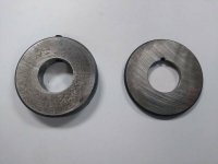
Also, could you post photos of both sides of the two rings that retains the reverse idler gear bearing, EE-1098 and EE-1100? I want to verify that EE-1098 has a notch for the aligning pin and that the rings only contact the inner race of the bearing.

Thanks,

Cal
 
OK, How about the OD of the shifter fork shaft (EE-1101)? I'm trying to get an idea what the diameter of the plug is. Maybe you can measure the stub shaft ID at the end with the sleeve bearing (EE-1097, shown in blue). (I added a drawing to post #2.)

It looks like 0.685" not counting the bronze sleeve.
IMG_20220401_182129247.jpg


Also, could you post photos of both sides of the two rings that retains the reverse idler gear bearing, EE-1098 and EE-1100? I want to verify that EE-1098 has a notch for the aligning pin and that the rings only contact the inner race of the bearing.

Yes, there is a notch for the alignment pin. It appears that the rings slightly rub the bearing outer races. You can see the scuff marks from the outer race in the second picture.
IMG_20220401_181934837.jpg IMG_20220401_181950909.jpg
 
Public Service Announcement: There are setscrews securing the idler shafts!

While prepping the headstock for re assembly I noticed two holes in the bottom (1st picture). When I looked in with a light I saw each had a setscrew. They are for locking the idler stub shafts in place. I was unaware they were even there. I got super lucky in that they were not threaded in deeply enough to engage the stub shafts because I just pulled them out with a slide hammer. I would have done damage if they were set properly.

I have not seen any mention of these set screws in any of the threads I have read. They are also not shown on the blueprints. I just wanted to put it out there for the next guy trying to pull out the idler stub shafts (reverse idler gear or tachometer).

IMG_20220405_124456849.jpg IMG_20220405_124432495.jpg IMG_20220405_124634720.jpg IMG_20220405_124651089.jpg
 
That’s interesting. I removed both shafts from the square dial machines I restored last year and there were no setscrews. I made a lever to push out the rear bushing, it bolted to the slider and had a spacer that went against the internal web in the headstock below the slider. Even so, I could not budge that bearing with at least 20:1 leverage. I used a big c-clamp to pull on the lever. There are some photos in my thread on the 59 rebuild.
 
That’s interesting. I removed both shafts from the square dial machines I restored last year and there were no setscrews. I made a lever to push out the rear bushing, it bolted to the slider and had a spacer that went against the internal web in the headstock below the slider. Even so, I could not budge that bearing with at least 20:1 leverage. I used a big c-clamp to pull on the lever. There are some photos in my thread on the 59 rebuild.
Here's a link to Dave's thread: Headstock Replacement for a 59 10EE
This is one of Dave's photos that shows one of the spots where HR found a setscrew hole:
282207d1584585299-headstock-replacement-59-10ee-img_0398.jpg


Cal


Back
Top