What's new
What's new

Hitachi WJ200 push button control issues

BHolcombe

Aluminum
Joined
Apr 15, 2019
Need some trouble shooting help. I installed a 3ph 3hp motor powered by a Hitachi WJ200 drive. Motor runs fine, starts/stops on the keypad controls.

I want to run push button controls and so I thought I setup the inverter to accept push button controls. In doing so I swapped the logic jumper from P24 to L, ran P24 through push buttons and set them to 1 and 2. I set C001 to 20 and C002 to 21, I also set A002 to 01. All according to spec and same as I have on another machine. Only, nothing happens.

I checked the P24 lead and it shows less than 1 volt, the same setup on the other inverter shows higher voltage at the P24 terminal Not sure what I’ve done wrong here but appreciate any troubleshooting input. Thank you!
 
So you basically followed what is on page 4-16?

What about A001? That sets the speed input source. Should be "01" to use the analog input.

The pot should use the 10V output as it's power source.
 
Yeah, followed that guide. A001 is set to 01.

Forgive my ignorance but where do I pickup 10v power?
 
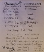
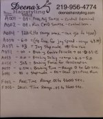
The WJ200 uses 24V IIRC, doesn't it? Do you have a frequency pot on your remote? It would help to know what all you have connected and where. I have a couple setup "cheat sheets" from when I set mine up, not sure if they will help you, but I'll add them. 'P24' terminal should be +24VDC, 'L' terminal should be ground.

20200530_032143.jpg 20220421_103948.jpg
 

Attachments

  • 20200527_225620.jpg
    20200527_225620.jpg
    85.5 KB · Views: 17
By 'push button control' you mean three wire, two buttons: red button momentary on for run, black button often momentary break for off?
 
Yeah, followed that guide. A001 is set to 01.

Forgive my ignorance but where do I pickup 10v power?

It is on the terminal strip when set to use external pot. Check page 4-87 in your manual, and pages from 4-5 onward.. "H", "O", and "L" are the terminals you want. H is 10V (goes to top of pot, the CW end), O is the input (from the slider of the pot), and L is the "ground" for the control (goes to CCW end of pot).

I looked around for the settings for momentary action of the buttons, but was limited for time and did not find them. I am pretty sure that is possible, so look around in the wiring section (section 4) and maybe in the parameters section (3).

Look at page 3-86, there it shows the run and stop button function select codes. You would have start, stop, and a direction switch.
 
Most vfds have a special programming mode to emulate a motor controller using the old two button station. Teco calls it 'three wire control' an Hitachi probably has the same feature by some similar name.
 
Resolved, setting C012 needed to be set to 01. I spoke with Hitachi tech and the fellow who helped me was excellent.

Thanks also for the help, gents!
 
It's been so long since I set mine up I forgot about all those other settings. Just looked back in the manual and found C012 - setting for whether the switch is active when NO or NC. I had a problem when I moved my milling machine recently - I had disconnected the remote panel for the move and had powered up the VFD with it disconnected before rewiring it, which apparently removes some of the settings. The jog function was working backward - it would only jog when I hit run. I noticed that the machine worked correctly if I held the jog button down. So I just swapped to the opposite set of switch leads. Totally forgot that was a switchable option.
 
Ah, very odd. These electronics know how to keep life interesting, Hah.

While we’re on the subject of this inverter, does anyone know how to hookup a run indicator light to the 24v outputs? It’s not obvious based on the manual but my switch has a LED feature.

I’ve got an external braking resistor on the way also, trying to knock the braking down to around 1-2 seconds with larger saw blades on the machine.

Check these sections, should get you sorted.

20220422_092644.jpg 20220422_092706.jpg
 
Having the run light during on is eluding me. I tried plugging into ‘11’ and CM2 with C021 set to 00, nothing. Tried AL1/2 and AL0 with c026 set to 00, nothing. Tried 01 also, nothing
I tested the led, it works.
 
Plugging in an LED indicator light. It’s an Eaton model M22 LED W 12-30VAC. Shows 5-14mA so it’s under the 50mA max.
 
Solved:

Hitachi tech recommended jumping CM2 to L, running P24 to light and 11 as common with C21 set to 00


Back
Top