What's new
What's new

Pratt & Whitney 12C Restoration Pictures

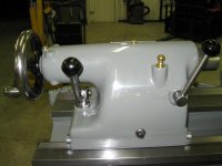
That looks a really nice machine to work on. “ DSG’s “ were like that. Everything came apart as it should. You didn’t have to fight the machine. Another thing - any spares you ordered from them fitted perfectly, nothing needed any alterations.That wasn’t my experience with other manufacturers.

Regards Tyrone.

I once looked at a 1307 DSG but decided it had too much wear for me to deal with at the time. Any favorite model you have? Are the older ones better than the newer?
 
I once looked at a 1307 DSG but decided it had too much wear for me to deal with at the time. Any favorite model you have? Are the older ones better than the newer?

I liked the machines with squared off headstock. The ones with the flat headstock cover not the domed headstock cover. Having said that anything from “ DSG “ was top notch “. They never made a bad machine. The CNC machines that came out around the time of the “ Monarch “ tie up were excellent machines also.

“ Lang “ was another really excellent British lathe, they were made in Scotland, they’re also a nation with an excellent reputation in the engineering world.

If we’re talking really big lathes “ Craven “ and “ Swift “ took some beating.

Regards Tyrone.
 
The top left of this picture is the banjo bracket. Next to the banjo is the mounting bolts, but there may be a couple others that are in the container in the background. Next to that is the ratio shifting lever and detent which goes in top of the gear box just under the removable cast tray. This connects to the feed reversal clutch linkage. One part that is not pictured in the long feed reversal control shaft. This shaft goes clear to the other end of the machine into the end rod bracket. Inside of this is a worm that turns in a babbitt casting. This provides the motion for shifting the feed reversal clutches. Next on the top row is the oil piping and manifold, and cover tray.

The middle row of this picture is the feedbox oil pump, cone shaft, screw and feed drive shaft with the low, medium and high gear, and the cone gears. Note – more needle bearings.

The lower portion of this picture shows the rocker shaft and the rocker and plunger handle.
 

Attachments

  • IMG_1888.jpg
    IMG_1888.jpg
    87.8 KB · Views: 18
In the middle of the first picture is shown the intermediate shaft assembly and the medium and high speed drive gears. Also pictured is the ABC shifting mechanism and the thread and feed shifter. Next to that is the oiler and oil piping for the rocker – and, of course, a sight glass.

The second and third pictures are just closer views of the shifters.
 

Attachments

  • IMG_1889.jpg
    IMG_1889.jpg
    88.3 KB · Views: 11
  • IMG_1890.jpg
    IMG_1890.jpg
    90 KB · Views: 10
  • IMG_1891.jpg
    IMG_1891.jpg
    82.6 KB · Views: 11
The first three pictures are additional views of the shafts and gears. The fourth picture is of the rocker assembly (and more needle bearings inside.) The last picture is of the empty gear box.

This is a fairly simple box to disassemble in part because two of the shafts and four of the gears are in the bottom of the ratio box on the back of the lathe.
 

Attachments

  • IMG_1895.jpg
    IMG_1895.jpg
    96.6 KB · Views: 14
  • IMG_1897.jpg
    IMG_1897.jpg
    90.5 KB · Views: 14
  • IMG_1894.jpg
    IMG_1894.jpg
    88.2 KB · Views: 13
  • IMG_1893.jpg
    IMG_1893.jpg
    87.7 KB · Views: 12
  • IMG_1892.jpg
    IMG_1892.jpg
    87.5 KB · Views: 12
The first picture is another picture of the empty gear box. I’m getting ready to knock out the rocker location pins in the front of this box. They are through-drilled. A brass punch and a small hammer are all it takes to knock them out. They are all in a row just above the opening. Knocking these pins out makes painting preparation easier.

The second picture is of the inside of the box painted with Glyptal. I did the same with the apron and the apron front cover.

The third picture shows the beginning of paint preparation.

The last picture is of various parts being cleaned for reassembly. All new bearings were installed in the feedbox including the two angular contact bearings on the lead screw. All bearings were also replaced in the apron.

Disassembly of the feedbox is done pretty much by starting from the top and continuing down to the bottom gears and shafts. You must, however, pull the shifting levers which have an inner and outer piece. The inner piece is clamped with an allen bolt and mounted on a keyed shaft. You loosen the allen bolt and the front portion of this shifter will pull out through the casting.

Something that I noted in an earlier post was a comparison between this feedbox and the American 16x54 Pacemaker’s. The shafts and gears in the Pratt & Whitney are fairly large for the lathe’s size. The Pacemaker has internal shafts and gears that are just about this same size. I believe the Pratt & Whitney turns the feedbox at a slower rate putting it under more pressure for a given load. The power comes in the apron using a very expensive worm gear. The result of this is a very smooth drive with less noise and vibration. By contrast the Pacemaker spins the feedbox faster with a greater reduction of gearing in the apron - much like a large truck uses a really low rear-end. It is made for power. This is an example I believe of the different choices that these manufacturers made based on what they were trying to achieve. Not really better or worse – just a different end goal.

Just something I’ve observed in working on these two machines.
 

Attachments

  • IMG_1901.jpg
    IMG_1901.jpg
    91.3 KB · Views: 35
  • IMG_1900.jpg
    IMG_1900.jpg
    93.1 KB · Views: 36
  • IMG_1899.jpg
    IMG_1899.jpg
    95.9 KB · Views: 35
  • IMG_1896.jpg
    IMG_1896.jpg
    91.5 KB · Views: 35
Are you using Glyptal 1201 from quart containers, or any of the sprays ? And are you brushing it on ? I saw some of your other machines, looks like you are using it on table tee slots and such, is that right ?

Side question too, I remember you wrote somewhere about your paint prep and finishes. You mentioned about using a heavy primer that acts like filler. Last week a fella with user name Lucaselef mentioned something similar in the South Bend section. I was wondering if it was the same stuff you used. His main comment here:
My 1959 Heavy 10 Toolroom Lathe

It had been on my mind how thicker stuff managed to spray through a gun, and he mentioned and linked a gun with a larger nozzle here:
My 1959 Heavy 10 Toolroom Lathe
 
The first three pictures are additional views of the shafts and gears. The fourth picture is of the rocker assembly (and more needle bearings inside.) The last picture is of the empty gear box.

This is a fairly simple box to disassemble in part because two of the shafts and four of the gears are in the bottom of the ratio box on the back of the lathe.

High quality components. What did the machine sell for back in the day ? I’ll wager they weren’t cheap.

Regards Tyrone.
 
Thanks for posting such detailed pictures. I got my 12C a while back.
It's in really nice mechanical condition but terrible cosmetic shape having spent a few years outside under a tarp. (not me)
Your pics and descriptions should be of great help when I start the clean up.
 

Attachments

  • IMG_6811.jpg
    IMG_6811.jpg
    94.6 KB · Views: 42
Are you using Glyptal 1201 from quart containers, or any of the sprays ? And are you brushing it on ? I saw some of your other machines, looks like you are using it on table tee slots and such, is that right ?

Side question too, I remember you wrote somewhere about your paint prep and finishes. You mentioned about using a heavy primer that acts like filler. Last week a fella with user name Lucaselef mentioned something similar in the South Bend section. I was wondering if it was the same stuff you used. His main comment here:
My 1959 Heavy 10 Toolroom Lathe

It had been on my mind how thicker stuff managed to spray through a gun, and he mentioned and linked a gun with a larger nozzle here:
My 1959 Heavy 10 Toolroom Lathe

I do use Glyptal 1201 in both quart and spray. I prefer the quart as it is a little thicker. I usually just brush it on the inside of a gear box then I always make sure to “bake” it. I do this by wrapping it in a welding blanket and dropping a 100-watt light bulb inside, leaving it over night or so. This speeds up the curing process. If you do use it in a gear box, I recommend waiting until it is hard enough that you can’t stick a fingernail in it before you add oil. Also, you must make sure that whatever you apply it to is completely degreased. I use it wherever I want a really tough finish or to seal up a casting. It sheds oil and dirt easily. The only case I know of where it failed was many years ago, I had a friend who used it in an engine. He either didn’t get it clean enough or let it dry long enough because it peeled off causing a lot of problems. But I’ve never had a problem with it.

Two other things about Glyptal…I never mask anything off in a gear box because I want to see where this stuff goes. If you get any of this on a surface such as a bearing bore, you want to be able to wipe it off with lacquer thinner and a cloth. Once it is baked on, it can be very tough to remove. The other is if you paint t-slots with it, be sure to paint only the bottom so there won’t be any clearance problems with t-nuts.

Below I’ve included a few pictures of where I’ve used it.

As for the high build primer, it is a product I use. I also sometimes use Evercoat high build primer in a can for small parts. The only thing I would say about using a high build primer is that you can use multiple coats and it will conceal minor blemishes. However, I try to guard against getting it too think as it is pretty soft, and I believe it leaves a part a little more vulnerable to chipping. It is really not a substitute for a filler, but rather a finish product.

I plan to conclude my restoration thread with a little bit on how I paint my machines.
 

Attachments

  • IMG_0440.jpg
    IMG_0440.jpg
    96.4 KB · Views: 47
  • IMG_0439.jpg
    IMG_0439.jpg
    99.1 KB · Views: 50
  • IMG_0438.jpg
    IMG_0438.jpg
    96.8 KB · Views: 47
  • IMG_0437.jpg
    IMG_0437.jpg
    96.5 KB · Views: 46
  • IMG_0436.jpg
    IMG_0436.jpg
    94.9 KB · Views: 48
Thanks for posting such detailed pictures. I got my 12C a while back.
It's in really nice mechanical condition but terrible cosmetic shape having spent a few years outside under a tarp. (not me)
Your pics and descriptions should be of great help when I start the clean up.

Good luck on your clean-up. As far as my posts, if it helps one Pratt & Whitney owner or helps keep one Pratt & Whitney running, I will be pleased. They are one of the great machines and worthy of your efforts.
 
One other note about the compound, it seems to have been made out of steel or some kind of forging. Anyway, it isn't cast. This makes it a little more difficult to deal with for anyone who is planning to machine the top. Not sure why Pratt & Whitney did this, but I do know that this a 3,400 lb. machine is as ridged as any I have.

Found this little bit of info on the compound. On page 3 bulletin 15 of the model C brochure it states "tool rest slide is a steel forging to prevent breaking out T-Slot under heavy pressure as so often happens when cast iron is used." It is mentioned again on pg 12 last paragraph that the tool side is a drop forged steel part. There you have it direct from P&W.
 
Tonight’s postings are about the tailstock including a test I ran.

The first two pictures are of the tailstock casting. Also note the two large taper pins that hold the back casting. The third picture is a front view of the tailstock. The next picture is a rear view of the tailstock.
 

Attachments

  • IMG_1447.jpg
    IMG_1447.jpg
    94.3 KB · Views: 19
  • IMG_1444.jpg
    IMG_1444.jpg
    83.8 KB · Views: 18
  • IMG_1445.jpg
    IMG_1445.jpg
    89.5 KB · Views: 17
  • IMG_1446.jpg
    IMG_1446.jpg
    92.6 KB · Views: 17
  • IMG_1442.jpg
    IMG_1442.jpg
    93.1 KB · Views: 20
The second picture in this set is of the length of the quill. The third picture is the nut end of the quill. The last picture is of the taper end of the quill. The quill is a foot long but has around a 5” travel. The remainder stays in the tailstock.
 

Attachments

  • IMG_1449.jpg
    IMG_1449.jpg
    96.9 KB · Views: 9
  • IMG_1448.jpg
    IMG_1448.jpg
    94.5 KB · Views: 9
  • IMG_1450.jpg
    IMG_1450.jpg
    93.8 KB · Views: 9
  • IMG_1451.jpg
    IMG_1451.jpg
    90.2 KB · Views: 9
The first picture is of the tailstock clamping assembly. Note the four-point clamping. It clamps all four corners of the tailstock evenly. Also note the holes in the tailstock base. These holes are for springs and mounts that look like fingers on a steady rest with ball bearings. They are held in these holes by a small set screw that allows them to move up and down. This greatly decreases the amount of weight on the tailstock ways. It also greatly reduces the effort to move the tailstock. More on this later.

The next picture is of the wedge clamp for the quill and the handle and its eccentric. The third picture is of the tailstock handle assembly. This has a cam assembly in the handle that allows it to break over when it is all the way on. This allows the clamping force to be duplicated exactly.

The last two pictures are of the finished tailstock.

I did replace the little bearings in the base of the tailstock and way wipers. I also put a new screw and nut in the tailstock even though the original didn’t have too much wear. I just wanted it to be new.
 

Attachments

  • IMG_2058.jpg
    IMG_2058.jpg
    87.7 KB · Views: 35
  • IMG_2057.jpg
    IMG_2057.jpg
    86.5 KB · Views: 36
  • IMG_2052.jpg
    IMG_2052.jpg
    89.6 KB · Views: 31
  • IMG_2051.jpg
    IMG_2051.jpg
    88.1 KB · Views: 30
  • IMG_2050.jpg
    IMG_2050.jpg
    90.5 KB · Views: 32
These next pictures are of the tailstock quill alignment. For these measurements, the tailstock and quill were fully clamped. The first two pictures are of the vertical alignment, back to front of the quill. The second two pictures are of the horizontal alignment, back to front of the quill.
 

Attachments

  • IMG_0456.jpg
    IMG_0456.jpg
    81.6 KB · Views: 23
  • IMG_0455.jpg
    IMG_0455.jpg
    82.4 KB · Views: 23
  • IMG_0454.jpg
    IMG_0454.jpg
    80.2 KB · Views: 23
  • IMG_0453.jpg
    IMG_0453.jpg
    86.2 KB · Views: 25
The first picture is of the quill unclamped and force applied downward then zeroed. The second picture is of the quill clamp applied. This reading will vary slightly depending on how much force is used on the quill clamp, but not by much.

I consider these numbers to be really good for an old lathe. I think part of the reason that the tailstock is in good shape may possibly be due to the rollers in the tailstock base. So I did another test for this post.
 

Attachments

  • IMG_0459.jpg
    IMG_0459.jpg
    83.4 KB · Views: 18
  • IMG_0460.jpg
    IMG_0460.jpg
    82.6 KB · Views: 18
The test involved four machines in the shop – the Pratt & Whitney, the Toolmex, the Monarch 10EE, and the Southbend Heavy 10 (as pictured).

I used the spring hanging scale (also pictured.) I attempted to use it to measure the force it takes to move each one of these tailstocks from a standing start and also while they are moving. I attached the hook end of the scale to the center portion of the handwheel on each lathe. Each tailstock and its ways were oiled with Schaeffer 160 Moly Slide and Way Lube (ISO 68). The results of this test as shown in the last picture may explain the low wear in the Pratt & Whitney tailstock

As you can see it doesn’t take much more effort to move the Pratt & Whitney’s tailstock than the Southbend Heavy 10’s even though the Pratt & Whitney’s tailstock is over 100 lbs. Maybe this helps explain the lack of wear or maybe it just wasn’t used much. I do believe other machines use rollers in the tailstock, but I can’t remember which ones.
 

Attachments

  • IMG_0441.jpg
    IMG_0441.jpg
    98.2 KB · Views: 41
  • IMG_0444.jpg
    IMG_0444.jpg
    94.7 KB · Views: 40
  • IMG_0445.jpg
    IMG_0445.jpg
    93.8 KB · Views: 38
  • IMG_0461.jpg
    IMG_0461.jpg
    96 KB · Views: 35
  • IMG_0462.jpg
    IMG_0462.jpg
    42.1 KB · Views: 38
Found this little bit of info on the compound. On page 3 bulletin 15 of the model C brochure it states "tool rest slide is a steel forging to prevent breaking out T-Slot under heavy pressure as so often happens when cast iron is used." It is mentioned again on pg 12 last paragraph that the tool side is a drop forged steel part. There you have it direct from P&W.

Thanks for looking for this information and for posting it.


Back
Top