What's new
What's new

Project Schaublin 135

Well that plan won't happen unless any of you out there can suggest a decent in-line connector system that has pins that are actually big enough to solder the feed wires to, the connectors I bought although rated to 7.5A each pin are just too small and close to really be practical to solder anything other than small wire to so they are going back.

Any suggestions for a decent man size in-line connector system very welcome :)

IMG_4451x.jpgIMG_4453x.jpg
 
Being scorching hot outside it seemed an opportune time to head to the 'repair shop' and do some more on the 135.
I used a block and tackle bolted to the roof joists to lift the motor from a pallet truck onto the work bench and now the motor has been completed the reverse is straightforward, I also have another fixing point above the 135's motor end of the base unit and after moving the motor from the work bench down onto the pallet truck and back over to the lathe the job to re-install the motor commenced.

I've bolted the motor pivot plate to the motor, think when I took it out I removed it before taking the motor out of the base unit, think it will go through with a bit of juggling.

I made a sled out of scrap wood with a thick piece of 12mm steel running under the OSB to support the motor weigh, braced the whole thing against the opening so hopefully the motor will slide but the sled will stay in place ...

IMG_4469x.jpg

IMG_4470x.jpg

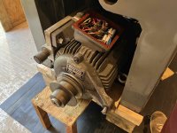
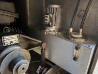
I got the motor about half way into the base unit and ensured it was stable and then proceeded to sort the wiring out, I re-terminated all the wires, checked them over and labelled them up making a note of the new numbers, the original wires had a number tape wrapped around each which had become super sticky and very dirty so these came off, the wires cleaned, and new ring terminations were applied on the 7 wires for the motor windings and earth link, and ferules on the 4 wires connecting to the brake and something else (not sure what that is).

IMG_4472x.jpg

IMG_4471x.jpg

Checked all the connections and have now left it till tomorrow when have fresh eyes to ensure the wires are on the right terminals. If this is all good will close up the terminal cover and see if I can get the motor onto its mountings ...
 
Wiring double checked and the terminal box closed up.

I was pleasantly surprised that the motor slide with a fair amount of shove into the right position to be rotated so the mounting plate spindle dropped into the mounting cradles, its weird sometimes that the jobs you think are going to be hard turn out way simpler, and those easy ones are right little b-ggers!

The rear cradle cap was a little tricky to get to, guess maybe via the suds end might be easier but I have not cleaned this yet so would look like a coalminer if I went in that end. Found if the motor is lowered down on the adjuster it makes it easier and the human brain is brilliant at working out from feel alone where everything is, anyway got them nipped up nice and tight. Motor slides for and aft on the shaft and there is some play on the adjuster to allow this, once the belts are on will work out the position and nip the grub screw up on the motor mount to secure the position.

IMG_4474x.jpg

IMG_4475x.jpg
 
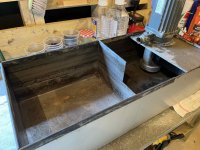
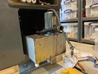
Bit the bullet and cleaned out the suds compartment, as good as I can get it and way better than when it arrived!

I remember when removing the tank and pump that I was unable to remove the pump by itself as there was not enough height to clear the pump pickup from the tank, got me thinking that maybe having the suds tank on runners might help sliding it out when full or needing a clean or coolant change, anyone dome something similar or am I barking mad?

Cleaner now ...

IMG_4476x.jpg
 
Interesting I was not aware that some makers included a roller or sliding suds tank, only had a Hardinge and this 135 so my experience is low, anyone got any pics of this sort of system I could use for bedtime reading?

A roll around system sounds like a nice idea, maybe when I find a sad looking Deckel FP1 or a Schaublin 13 mill I will adopt this but with only this lathe it might be a bit of an overkill.

I know there is almost no chance but if anyone does know of an FP1 or 13 is renovation condition close to the UK for sale please let me know :)
 
Suds tank, yuk not a fun job but today it happened and after an hour or so with petrol and loads of rags and brushes the tank is clean enough to be put back into service, assuming the pump actually works!

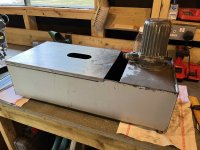
There is a lid with an enlarged cut out for the drain hose to go through and deliver its discharge into the first tank, the lid is a drop on fit and whilst I'm sure the 135 is not a quiet lathe having what can only be described as an out of tune tin drum resting in the base of the cabinet is not going to make it any quieter.

I had some rubber edge strip which fitted nicely over the lip of the tank and allowed the lid to fit nice and snug with no resonance. While I had the edge strip I also edged the drain hose opening and also cut a new relief for the suds feed hose which when attached to the pump pushes the lid down, now it clears the lid and tidies up the lid openings.

Going to see if there are rubber feet which will fit over the three metal studs which are welded to the base of the tank, again these are not going to do anything to resonance noise when that socking great motor is whirring round!

Pics of progress today ...
IMG_4479x.jpg

IMG_4481x.jpg

IMG_4482x.jpg

IMG_4484x.jpg

IMG_4486x.jpg

IMG_4485x.jpg
 
The rubber feet which I ordered arrived today, opted to go with the cream coloured ones as these have a flat base whilst the black ones have a curved base, felt as the metal feet on the suds tank were flat the cream rubber ones should match. Had to shorten them down using a band saw so they fitted nicely, overall the height still allows the whole tank to be removed with pump in situ which was the plan.

I may be making a sweeping assumption here that the tank never had rubber feet but guess as its 50 years old that maybe it did have when new and they have just perished and been lost or discarded over time, anyone know if the 135's suds tank were fitted originally with rubber feet?

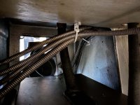
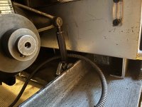
Drilled and tapped a few holes inside the cabinet to fix conduit/cable supports so that the cables were held clear from any snagging and kept away from the suds tank etc. One above the tank gathers the cables as they leave the electronics cabinet and one on the back face of the lathe cabinet where there is a support, albeit a curved piece of metal which was not really doing much. Used the threaded hole on the back of the cabinet (M8) and made up a small bracket to fix a cable tie to and clipped all the cables to it.

Fitted the coolant feed pipe and re-connected the suds pump, the connections on the cable ends have all been replaced with new soldered ring ends and marked sleeves.

Slid the tank in and ready for testing the motor and eventually filling with 'milk'.

IMG_4489x.jpg

IMG_4491x.jpg

IMG_4490x.jpg

IMG_4495x.jpg
 
Last edited:
OK the guy who designed the oil tank mounting system was a sadist, three bolts in a space where you can barely get a hand in let alone a position that any yoga expert would consider madness, I understand now why only one bolt was actually fitted when I got the lathe!

The tank went in and out 5 times before I was able to bend the feet into a position that allowed the holes to line up to kick of with, again you cannot see if they are aligned and have to do the whole thing by feel with copious amounts of pain and no doubt a trip to the chiropractor too ....

Anyway once I got the alignment right and managed to get all three bolts in by hand as far as they would go the time to do them up threw yet another challenge, getting an Allen key in there is impossible, I ended up grinding the short end of a key close to the bend so I could get it to locate, then on the two bolts at the back of the mount you literally had about a quarter turn available to tighten them as you had no room to work, it took me almost 45 minutes to do up 3 bolts £$%&!!!!!!

Hope it does not need to come out anytime soon but it's in now (better not leak!).

Hooked up the new tank vent pipe, using the spare port now not needed as the Variator has no oil feed return, connected up the head gear drain via the 12mm OD push fit pipe back to tank and started to plan the 10mm OD pipe route up to feed the head gear from the pump.

Painful but done, god bless Schaublin ...

IMG_4497x.jpg

IMG_4499x.jpg

IMG_4500x.jpg
 
OK the guy who designed the oil tank mounting system was a sadist, three bolts in a space where you can barely get a hand in let alone a position that any yoga expert would consider madness, I understand now why only one bolt was actually fitted when I got the lathe!

The tank went in and out 5 times before I was able to bend the feet into a position that allowed the holes to line up to kick of with, again you cannot see if they are aligned and have to do the whole thing by feel with copious amounts of pain and no doubt a trip to the chiropractor too ....

Anyway once I got the alignment right and managed to get all three bolts in by hand as far as they would go the time to do them up threw yet another challenge, getting an Allen key in there is impossible, I ended up grinding the short end of a key close to the bend so I could get it to locate, then on the two bolts at the back of the mount you literally had about a quarter turn available to tighten them as you had no room to work, it took me almost 45 minutes to do up 3 bolts £$%&!!!!!!

Hope it does not need to come out anytime soon but it's in now (better not leak!).

Hooked up the new tank vent pipe, using the spare port now not needed as the Variator has no oil feed return, connected up the head gear drain via the 12mm OD push fit pipe back to tank and started to plan the 10mm OD pipe route up to feed the head gear from the pump.

Painful but done, god bless Schaublin ...

View attachment 369002

View attachment 369003

View attachment 369004
put 2 studs in?
 
Sorry Pat did not read your message properly, I would have to put three studs in as don't like holes without things in them especially as that was how it was made.

Certainly a stud would make the hole alignment easier but you still have to get a spanner on the nuts to do them up and access is pants to be fair. Not sure there is any other options as its tucked away and access is tight regardless.
 
At the stage now where I can move the 135 to roughly where it will live in the 'repair shop', I call it that as it rings a bell with the better half as seems it is a wiser use of words to describe a place where things get made (better) - I'm off to the workshop just does not have the same ring!

Still have a few jobs to do before I can juggle it down onto the new feet and get it levelled as close as I can with a spirit level as don't own and cannot afford a 'special' lathe level.

Hope to get the new Variator assembly in very soon and have a rotary phase convertor on order to change my supply to 3p 400v. A few items to tighten up and the collet closer assembly needs fitting, hoping then to test the motor, oil pump and suds pump and lubricate the lead screw.

The galvanised sheeting which was made for my Hardinge to fit with will require some modification to work with the 135's chip tray so will be fabricating this as one of the final jobs too.

IMG_4501x.jpg
 
Question:

I've taken the plunge and ordered a 5.5kw Rotary Phase Converter so my 1ph 240v supply can be converted to run the 135, ironically this item was almost the same £ as the lathe! Hey ho guess now I can buy a 3ph mill and not have to worry - so anyone got a ropy old Schaublin 13 for sale?

Anyway back to the question, I have been told I should add a 3ph breaker between the converter and the lathe to protect any fault in the lathe damaging the convertor, each phase should be protected by a fuse around 1.3x the max individual phase current, so what rating fuse wise should I use for each of the three phase feeds?
 
Thermite seems you were spot on, found in the junk box that came with the 135 the switch/fuse isolator that was originally fitted and there are 3 x 20A fuses in the case ...

IMG_4519x.jpg

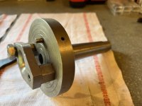
Also does anyone know if this is a 'normal' accessory for any lathe or a custom part that may have been made for a specific job on the 135 I have? It has a taper end that fits in the tailstock and the curved inverted dome on the front looks like its been subject to rotational friction so I'm assuming its a fixed type centre ...

IMG_4520x.jpg

IMG_4521x.jpg
 
Ah when I said came with the machine I did mean from whence I bought it which was in the UK although gather it went to the USA when new according to Schaublin.

I cannot see any info around phase current requirements in the manual or any documentation I have so will go with 20A per phase as this was how it was set up before and was used for some 15 years in this way. If anyone can verify either way the phase current requirements on the 135 I would be appreciated just to sanity check the current view that 20A is about right.

'Drilled balls' now thats a good possibility ... going in the keep box but not holding much hope as to a use right now.
 
Couple of updates, small ones but all part of the process.

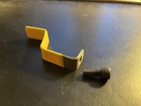
Having replaced the solid brass oil feed pipes to remove the banjo and copper washer leak issues (hopefully!) I needed to make a small retention bracket to keep the oil feed pipe that runs up to the top of the gearbox clear from any rotating belts etc.

I bent up a piece of galvanised steel and then dipped in something called 'Plastic Dip' if a liquid rubber coating that can be applied to almost any material and gives a soft feel surface which is easy to grip and slightly 'soft', its used to make handles on DIY projects or to replace broken ones from tools etc. I used it on a log splitter I made and decided to coat this bracket so it did not rub against the nylon oil feed pipe and split it over time.

Great stuff BTW and good to have a can spare for those jobs that need a nice touch and finish ...

IMG_4530x.jpg

IMG_4532x.jpg

My machine guru has drilled and tapped the two holes in the central Variator hub so that a grease nipple can be fitted in one hole and a dog nose grub screw in the other to allow the grease to fill the cavity inside the hub and not pressurise the seals in the process, bought a few options but ended up using the 8mm one and the wall thickness is 11mm so this seemed the best choice ...

IMG_4523x.jpg
 
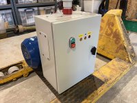
The 135 is 3 phase and in the UK its rare in a domestic location to have 3 phase, almost all homes have a single phase supply around 100A, my last lathe a Hardinge I converted to single phase with VFD's and motor swap but this really was not an option on the 135 so I needed a rotary convertor (rotary due to two speed motor in the 135). Did a lot of research and opted with the item in the pictures. Its compact for its output and the design allows the motor if required to be located in a different place to the main cabinet, something I might do.

Need to add a supply cut off and a three way fuse on the output to the 135, hoping I can mount these on the cabinet too with some minor surgery ...

IMG_4533x.jpg

IMG_4534x.jpg
 
Few parts arrived from Schaublin today, one is the coolant hose section which runs from the back of the chip tray to the coolant nozzle, naturally its flexible as it moves back and forwards and the original one I had was a braided clear hose which had split at the fitting end, was expecting the same hose but 'new' but guess being Schaublin you now get a very OTT hose - looks like a fancy hose you find in an F1 engine - yet this is only for coolant - wow ...

IMG_4536x.jpg


Back
Top