What's new
What's new

Full tear down and Rebuild of a 10EE Round Dial

Ok, so I tested each winding with my clamp meter by applying 120V ac across each one. I only got a few seconds before it blew the fuse each time on the extension reel I used. So these are possibly just start up amperage, but they do seem quite high. The motor does start to spin with each coil test.

So for coil 1-4 I got 47.8 AMps
Coil 7-10 I got 48 amps
coil 9-12 I got 47.8 amps
coil 6-3 I got 48 amps
coil 11-8 I got 47.8 amps
coil 2-5 I got 48 amps

Cal suggested that I purchase a cheap variable speed control for a motor, to use to check each winding at a lower voltage.

I also tested the clamp meter VS my Fluke 117 using one of the power leads for my Bridgeport.
The clamp meter consistently read high, but by carrying amounts.
IMG_8218.jpg
1.8 Vs 1.3 A
IMG_8220.jpg
1.4 VS .993 A
IMG_8222.jpg
1.2 Vs .835 A
IMG_8225.jpg
1.4 VS 1.2 A

So that is less than confidence inspiring for the clamp meter, but I dont think it explains such high values with the motor windings.
IMG_6473.jpg
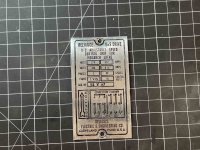
The name plate for the motor reads max 6.6 Amps at 440V isn't that spread over 4 windings in series?
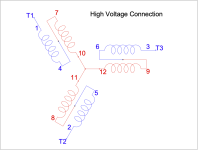
Screen Shot 2022-07-05 at 7.57.26 PM.png

It reads 13.2 amps at 220 V I believe thats across two sets of windings in series in parallel.
Screen Shot 2022-07-05 at 7.58.34 PM.png
So then with 120V with just one winding would that make sense for the higher amperage ?

Now, If I do some basic math with Ohms law V=IR, plugging in the measurements I recorded lets see if we can make sense of it all.

so 48AX0.7Ω = 33.6 V.
or I = V/R so 120V / 0.7Ω = 171A
or R = V/I so 120V/48A= 30Ω

None of the calculated numbers work out with the data I recorded. Something is clearly wrong.

Humm. If I take the numbers I got from one winding and multiplied it by 4 (for having 4 windings in series) I then get numbers that make sense for what I am reading.

33.6V x 4 windings would be 134.4V
120v / (.7Ω x4 windings) = 42.8A
120V / 48A x 4 windings) 0.625Ω

Does this make sense? Or am I just talking myself into thinking it does? Or have I just proven I'm off everywhere by a factor of 4? I think I need to calculate the equivalent for the numbers I got at @220 and @440 for a single coil if that makes sense.

FYI the wiring Diagrams are by Cal.
 
Last edited:
On a 3-phase motor, you're only looking at the current on one phase at a time. At full load, each coil sees 220 VAC, 6.6 A regardless of how the motor is configured. It doesn't matter if you're running from 440 or 220, each coil still get the same voltage. Two coils in series, the voltage is split across them. Two coils in parallel, the current is split between them.

At 120 VAC, the current should be no more than half the rated current, i.e. 3.3A. Ballpark we should see around 30 Ohms per coil, but you're seeing less than an 1 Ohm. Something is very wrong.

Cal
 
This does not make sense! It sounds like a shorted turn OR you have the windings mixed up in the 220 vs 440 conversion. Any reversal of a winding pair or using a winding from a different phase can act like a shorted turn.

You can test this by separating all the windings and repeat the test on each one. If they all test good and are equal, then we can do another test that will identify the correct connections to have the motor run on 220 volts.

In your situation where you are drawing a high current, you can put a 100 watt light bulb (old style filament bulb) in series with the winding to limit the current. This will limit your current to no more than 1 amp and should not risk blowing any of your components.

It is also odd that the motor should start to turn during this test. By connecting a single phase and no capacitors, you will not get the necessary rotating magnetic field to start rotating the armature. However, a shorted turn can act as a shaded-pole motor and give the rotor a little bump. But I think that this is unlikely.
In the test I just did above, applying 120Vac to each winding separately produced a consistent 47~48Amps on each one!

With 120 VAC applied to Winding 1-4 47A
With 120 VAC applied to Winding 2-5 48.A
With 120 VAC applied to Winding 3-6 48A
With 120 VAC applied to Winding 7-10 48A
With 120 VAC applied to Winding 8-11 47A
With 120 VAC applied to Winding 9-12 47A

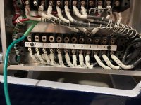
I then placed the Jumpers for the standard Low-Voltage wiring configuration
Screen Shot 2022-07-05 at 7.58.34 PM.png
T1 ~T2 0.8Ω
T2~T3 0.8Ω
T3~T1 0.8Ω

With the Megger I get
T1~ground >4000MΩ
T2~ground >4000MΩ
T3~ground >4000MΩ

Applying 120VAC across T1 and T2 I get 41A on each briefly before I trip the fuse on the extension reel. Motor just humms.
Applying 120VAC across T2 and T3 I get 41A on each briefly before I trip the fuse on the extension reel. Motor just humms.
IMG_8240.jpg
For what its worth, I have not touched these bottom motor winding terminals since I did my previous testing and has amperage on T3 in the 9Amp range after start up amperage around 40.

With no power to it and each winding independent of each other I get the following:
Winding 1-4 0.9Ω
Winding 2-5 0.9Ω
Winding 3-6 0.9Ω
Winding 7-10 0.9Ω
Winding 8-11 0.9Ω
Winding 9-12 0.9Ω

With this setup feeding with 120VAC:
IMG_8242.jpg
I Get:
Winding 1-4 I got 47.8 amps

I am a bit concerned about continuing to feed this much amperage for testing.

I am stumped. Cal suggested I order one of these Variable Transformers So that I can test using a lower voltage.

At this point, I agree, I think I need to start with the basic elements of it and go step by step, first verifying that none of the windings have a dead short. Then verify we have the correct connections to run on 220V. The question is why is the Amperage so high with 120 VAC applied to a singe winding?
 
Last edited:
I am curious about the tag on the motor that you showed us above. It talks about exciter volts, 3 phase motors do not have exciters! Does this motor have brushes? Do you have pictures of this motor from both ends? Do the windings look good? Is their color the same everywhere? Does the motor smell OK? Burned motors have a distinct acrid smell.

You don't need a variable transformer, the 100 watt filament bulb will do. Or you can use an old filament transformer from a tube type radio or TV. A transformer from a UPS will give a low AC voltage. Some wall wart power supplies produced AC, but they are not common.

I decided to try the same experiment on the 3 phase motor on my Bridgeport. It is a 2 HP motor wired for 230 volts and measures 2 ohms DC between phases.

DSC03039.JPG

I used my General Radio Variac which has voltage and current meters in the same box. At 50 volts, I get 5 amps current flow. The motor hums a little but does not turn as expected.

DSC03041.JPG

It is hard to get an accurate measurement of resistance at low values with an ordinary voltmeter. Often, the leads have more resistance than the windings. Also, DC resistance is not the measurement that you want in this case, you want VAR's (volt / amp reactance). In my example, my VAR reading is 10 ohms VAR. That is 50 volts divided by 5 amps. You can see that this is a long way from the 2 ohms DC resistance. You can do this measurement using the light bulb trick, you don't actually need a transformer.
 
I am curious about the tag on the motor that you showed us above. It talks about exciter volts, 3 phase motors do not have exciters! Does this motor have brushes? Do you have pictures of this motor from both ends? Do the windings look good? Is their color the same everywhere? Does the motor smell OK? Burned motors have a distinct acrid smell.

You don't need a variable transformer, the 100 watt filament bulb will do. Or you can use an old filament transformer from a tube type radio or TV. A transformer from a UPS will give a low AC voltage. Some wall wart power supplies produced AC, but they are not common.

I decided to try the same experiment on the 3 phase motor on my Bridgeport. It is a 2 HP motor wired for 230 volts and measures 2 ohms DC between phases.

View attachment 373798

I used my General Radio Variac which has voltage and current meters in the same box. At 50 volts, I get 5 amps current flow. The motor hums a little but does not turn as expected.

View attachment 373799

It is hard to get an accurate measurement of resistance at low values with an ordinary voltmeter. Often, the leads have more resistance than the windings. Also, DC resistance is not the measurement that you want in this case, you want VAR's (volt / amp reactance). In my example, my VAR reading is 10 ohms VAR. That is 50 volts divided by 5 amps. You can see that this is a long way from the 2 ohms DC resistance. You can do this measurement using the light bulb trick, you don't actually need a transformer.
First off, I really appreciate the support I've gotten with the from the forum here. Its amazing how deep the knowledge base is. Especially a big thank you to you and Cal for helping me so much with this!

This is an inline motor / generator setup, so the 3Phase AC motor shares a shaft with the DC generator and an Exciter is piggybacked on top. Currently neither of those are in any circuit, so I have it isolated to testing just the AC motor section. Motor smells ok. I just re-varnished it prior to assembly, but with the DC generator sharing the shaft, no way to pear in to see the windings unless I take it all apart.

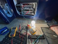
I just tested each set of windings individually using the light bulb method you described.
IMG_8323.jpg
It's amazing how hard it is to find an incadensent light bulb these days. I bought the only package of 100 watt bulbs my local Lowes had. Heck, I haven't even seen a traditional bulb in 10 years as are last two houses have had all florescent and now all LED lighting.

Here are my test results with this setup:
Winding 1-4 0.5~0.6 Amps
Winding 2-5 0.5~0.6 Amps
Winding 3-6 0.5~0.6 Amps
Winding 7-10 0.5~0.6 Amps
Winding 8-11 0.5~0.6 Amps
Winding 9-12 0.5~0.6 Amps

With the clamp meter fluctuating the same between .5 and .6 Amps, I'm guessing its probably somewhere between those two values, and I can put the Fluke 117 in there for more accurate measurements if needed, but they all appear to have the exact same value.

Whats next?
 
What is the voltage across the windings in the test? With the voltage and the current, we can calculate the Ohms VAR. My 2 HP motor had about 10 Ohms VAR, so your 5 HP motor should be about 4 Ohms VAR. My name plate current for 220 volts is 6 amps. That is the max load (2 HP) current. I would expect about 3 amps with my Bridgeport running. The vari-drive is very inefficient and probably wastes about 1 HP, so my motor is probably running at half load while my Bridgeport is idling.

The Ohms VAR is variable with the motor speed. It is low with the motor stopped and increases as the motor comes up to speed. That is why you get a slug of current when you start a motor. As the motor comes up to speed, the current drops.

Your 5 HP motor would probably draw just a few amps running, since the generator does not have much friction.
 
Ok, here is the results with another test run recording both amperage and voltage.

Winding 1-4 0.5 Amps 3.45 VAC
Winding 2-5 0.5 Amps 3.54 VAC
Winding 3-6 0.5 Amps 3.89 VAC
Winding 7-10 0.5 Amps 3.81 VAC
Winding 8-11 0.5 Amps 3.76 VAC
Winding 9-12 0.5 Amps 3.27 VAC

Its a 100 Watt, 15Ω light bulb
 
Last edited:
A 100 watt bulb running on 120 volts will draw .833 amps. 120 volts times .833 amps gives 100 watts. That is 144 ohms. A cold bulb may be 15 ohms, but a hot one will be higher. That is the beauty of using a bulb in an application like this, it is a variable resistor. You can use that feature to protect the equipment that you are testing.

Your motor has about 7 ohms VAR which seems reasonable. You cannot predict this exactly, it depends on the motor design. From your results, I don't think that you have a shorted turn.

You can run a 3 phase motor on single phase. The trick is that you have to get it spinning fast enough before you apply power. Some people use a pony motor. That is a small motor that gets the main motor spinning before the power is applied. Some people rig a pull starter attached to the motor. Once I tried starting a motor by kicking the shaft with my foot, I could get it going about half the time.

You could try this. Remove your capacitor box and just connect the power to 2 leads and leave the third lead unconnected. To eliminate the possibility of mislabeled wires, connect the power to leads 1 and 2, but you should leave leads 3, 7, 8, and 9 unconnected to anything. Don't let them touch. Spin the motor (direction does not matter) and apply the power. The motor should spin up or rapidly spin down (not coast down). If it rapidly spins down, then you did not get it spinning fast enough before applying power or there is something else wrong.
 
He's got access to both ends of all six coils and can apply power two any single coil. Each coil sees 220 VAC in service and should be able to take 120 VAC without breaking a sweat, but he's getting crazy amps when he tries that. I think that something's very wrong.

Cal
 
With a much needed break from dealing with the electronics, I decided to start working on the headstock. First step is removing the spindle lock.
image.jpeg
It's held on by two bolts, and two pins.
image.jpeg
Once the bolts where out, it took a bit of wiggling to free it from the pins. You can see the filters mark in the circle just above the hole center line at bottom.
image.jpeg
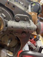
The business end of the locking pin is pretty haggard.
image.jpeg
There is a series of set screws on each end. Underneath a standard set screw is an additional dog point set screw on the handle end.
image.jpeg
In the center there is a nut securing another dog point set screw.
image.jpeg
The set screw and the nut came out together.
image.jpeg
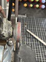
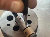
The handle is held on by a straight pin. It tapped out pretty easily. I started the process with a short pin punch, then transtioned to a longer one to get it out.image.jpegThe plunger pin is obviously bent. Since the end was mangled with no flat spot to push on, I used a starter punch in the about vise.
image.jpeg
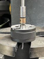
The handle end of the shaft is sitting in my Starrett bench block to hold the assembly steady.
image.jpeg
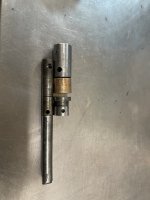
Here you can see that the plunger shaft is clearly bent.
 
image.jpeg
Upon closer inspection, I realized there is a pin holding each of the steel parts on that trap the bronze bushing. Those pins where ground flush with the exterior surface, so I used a starter punch and the bench block to tap them out.
image.jpeg
Once the two pins where out, I used the arbor press again with a long steel pin punch to press the shaft out of it.
image.jpeg
The center pin is soft steel. Its 0.3700" so it appears to be an undersized ⅜ pin.
 
Next up is removing the spindle. There are multiple other threads here on PM that describe this and found them all helpful. So the following is what I did after reading those.
image.jpeg
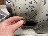
There is a single long setscrew / pin on the backside of the headstock that locks into a grove for the front bearing assembly to prevent rotation. It has to come out.
image.jpeg
Next, the drive pully is secured by a single large setscrew.
image.jpeg
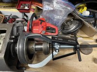
I then used my Posilock #106 puller to remover it with some random steel scrap that had come with the lathe to press against.
image.jpeg
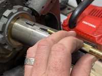
I used a brass pin punch to remove both of the woodruff keys that aligned the fully to the shaft.
image.jpeg
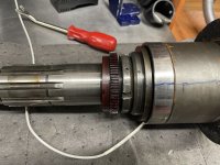
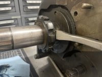
The notched ring that the spindle lock engages was on quite firmly. None of my pullers had the reach to remove it. So I used pry bar, slowly working my way around under it was loose. I then used a piece of hard wood to tap it off.
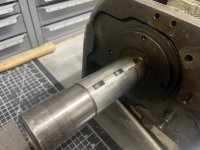
image.jpegYou can't press it off when you pull the spindle as it has a woodruff key under it as well. Same size as the other two.
image.jpeg
All 6 of the SHCS that hold the front retaining ring come off.
image.jpeg
I then threaded a 12" section of ⅜ all thread into each of the holes. Next I measured the outside distance across the rods. This minus ⅜" is the diameter of the bolt hole pattern.
image.jpeg
Pluging the diameter into the DRO on the mill along with the number of holes, gives me the bolt hole pattern. Just move to the coordinate the DRO says for each hole. It make the hole process go super quick, I used a ⅜" fostner bit and a ⅝" foster for the center hole.

The board gets slid over the ⅜" all thread and is secured on both sides by a nut and washer. I then passed the ⅝" all thread through the center hole in the board through the spindle and a scrap board on the back end.
image.jpeg
 
Before I pressed the spindle out, I spent a bunch of time inspecting the gears. With the woodruff key slots in the spindle point up, I found a set of reference marks on the tachometer gear.
image.jpeg
I then marked the top center line of the clutch gear as well.
image.jpeg
I also scribed "UP" above it. I then proceeded very slowly to press the spindle out. It took very little force with the wrenches to get it to move. Part of my concern was if the tach gear would fit through the bore, as my tach gear had no set screw on it.
image.jpeg
As I slowly moved it forward I would rotate the spindle to make sure the gear was free. It ended up fitting through with no issues.
image.jpeg
As the front bearing assembly pulled out, I used a sharpie to draw the top center line along the bearing unit. and also marked the top center of the head stock and the front bearing retainer.
image.jpeg
Notice the factory "V" mark that indicated the top center position of the spindle
image.jpeg
In addition to my Top center line on the clutch gear, I also scribed "front" and an arrow pointing to the bed side of the head stock to make sure it goes back in the correct direction.
image.jpegNote the indicator mark on the phenolic tach gear, the spindle bearing retainer and the spindle bearing assemblies all light up.
image.jpeg
The phenolic gear just pulls right off. It's only held on by a small woodruff key. Note in addition to the stop center scribe mark, I found that someone had put a second set on the gear and the spindle bearing retainer indicating where the woodruff key slot is. There is evidence that someone tried to press it on in the wrong spot before. Luckily its not broken! You can also see some damaged to the bearing lock ring that some must of used a screw driver on it, instead of using the correct hooked spanner wrench. So either the bearings have been replaced at somepoint, or someone adjusted the pre-load. No idea of which yet.
 
He's got access to both ends of all six coils and can apply power two any single coil. Each coil sees 220 VAC in service and should be able to take 120 VAC without breaking a sweat, but he's getting crazy amps when he tries that. I think that something's very wrong.

Cal
The fact that all are reading roughly the same, I'm starting to think that either its ok, and its just drawing a ton of current on 120 trying to power up with just a single coil energized in our testing, or something is wrong with the rotor side. I clearly dont know enough to know what is what with it at this point.
 
He's got access to both ends of all six coils and can apply power two any single coil. Each coil sees 220 VAC in service and should be able to take 120 VAC without breaking a sweat, but he's getting crazy amps when he tries that. I think that something's very wrong.

Cal
This is clearly a head scratcher! My thinking now is that the numbers on the leads are messed up. If you get that wrong, it can act like a shorted turn. My strategy forward will be to confirm that the connections and the numbers correspond. You can check this with a few measurements.

His current is not so crazy! In my case, with 10 Ohms VAR, if I put the normal 230 volts on the winding I will get 23 amps for an instant. Once the rotor starts turning, the back EMF will cause the current to decrease rapidly.

His situation is like a locked rotor situation. Something is preventing the rotor from spinning. A shorted turn can cause that, or his starting mechanism could be the problem. At this moment, it seems to be best to work step by step to eliminate each possible cause. I think that we have ruled out a shorted turn. Next is to check the wiring of the windings.
 
...

His situation is like a locked rotor situation. ...
You're right. (I realized that as I was waking up this morning.) If you look at the current in a single winding at startup it can easily be 10 times the full load current. Applying power to a single winding is the same thing.

His motor is turning, but it's drawing way more current than it should, four time full load current.

Cal
 
May I suggest you rig up a power cutout switch on that spindle lock. They put one on the later EE's and I know it saves me almost every time I use the lathe.
I like this idea. I have not seen any imagery of the switch setup. Mind sharing a couple of pics / part number for the switch? Thanks!


My strategy forward will be to confirm that the connections and the numbers correspond. You can check this with a few measurements.

his starting mechanism could be the problem. At this moment, it seems to be best to work step by step to eliminate each possible cause. I think that we have ruled out a shorted turn. Next is to check the wiring of the windings.
Suggestions for how to do this? I have confirmed I have continuity between all of the winding pairs. I was pretty diligent in the use of wire labels to make sure I keep them same as factory, but would be good to confirm. Thanks.


Back
Top