How to install the app on iOS
Follow along with the video below to see how to install our site as a web app on your home screen.
Note: This feature may not be available in some browsers.
You are using an out of date browser. It may not display this or other websites correctly.
You should upgrade or use an alternative browser.
You should upgrade or use an alternative browser.
Difference between cylindrical boring bar and boring bar with flat
- Thread starter M Code
- Start date
- Replies 12
- Views 1,442
Finegrain
Diamond
- Joined
- Sep 6, 2007
- Location
- Seattle, Washington
The difference is the boring bar without flats is a PITA to install, while the one with flats isn't  .
.
I don't understand your 2nd question .
.
Regards.
Mike
 .
.I don't understand your 2nd question
 .
.Regards.
Mike
Thanks,The difference is the boring bar without flats is a PITA to install, while the one with flats isn't.
I don't understand your 2nd question.
Regards.
Mike
I meant if I install the boring bar inside a socket where the socket is mounted on the turret, this boring bar needs to be flat so it can be hold with the screw?
PITA you mean like easyfix from Sandvik ?
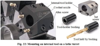
The boring bars also have cylindrical geometry but these have longitudinally-milled flat surfaces at the top (towards the insert face) as well as at the bottom (opposite to the insert face), as shown in Fig. 22(a). Tightening by set screws is done against one of the two flat surfaces. The tightening screws can be a part of the sleeve (in which case the boring bar is tightened against the sleeve, and the sleeve is tightened against the tool holder, independently), or the sleeve can have a longitudinal slot or clearance holes through which the set screws of the tool holder pass and press against the flat surface of the boring bar, thus simultaneously tightening both the sleeve as well as the boring bar against the tool holder. Figure 22(a) shows some common sleeve designs. The slot-type and the clearance-hole-type sleeves do not have flat surfaces on the circumference, as the flat surface of the boring bar is used for tightening. When the wall thickness of the sleeve is inadequate to safely accommodate set screws, the sleeve has to be designed as clearance-hole type or slot type.
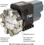
Figure 22 explains how an internal tool of cylindrical cross-section such as a drill bit can be mounted on such a turret, with the help of an internal-tool holder and a bushing (also called, turret sleeve). The outer diameter (OD) of the bushing matches with the bore of the internal-tool holder, and the inner diameter (ID) matches with the tool it needs to clamp (that is how the bushing is selected among various available sizes). The four allen screws at the top of the tool holder are tightened in the corresponding threaded holes on the turret. The two set screws on the side of the tool holder are tightened against the flat surface of the inserted bushing (Set screws are fully-threaded screws without a conventional head. One end has a recessed hexagonal socket for tightening with an allen key. It is designed to go fully inside the corresponding threaded hole). The bushing has a longitudinally-milled flat surface on its circumference (shown at the top of the bushing in Fig. 22) which is brought under the set screws by suitably rotating the bushing before tightening the screws. The bushing also has a narrow longitudinal slit along its wall at an angular position orthogonal to the flat surface (on the right wall of the bushing in this figure, which will come at the bottom after assembly). It is called a split-type bushing. Split-type design ensures good gripping due to spring action. Some other types of commonly-used bushings are described next. The protruded parts on the left face of the tool holder are nozzles for coolant.
Panza
Stainless
- Joined
- Oct 23, 2005
- Location
- Lillehammer, Norway
You can get round bars from Sandvik along with easyfix sleeves. The bars have a small groove which aligns the bar perfectly with a springloaded ball in the holder. The sleeves are sealed too.
Panza
Stainless
- Joined
- Oct 23, 2005
- Location
- Lillehammer, Norway
Yes, great quality made in Sweden. Worth the money IMO.This means that the bar as well as the matching sleeves both have to be purchased from them.
Yep, they are excellent bars.Worth the money IMO.
Similar threads
- Replies
- 1
- Views
- 240


