daryl bane
Titanium
- Joined
- Mar 12, 2002
- Location
- East Texas
Follow along with the video below to see how to install our site as a web app on your home screen.
Note: This feature may not be available in some browsers.
Thanks Daryl, I'm interested in where/how you made the transition between the 2 colors, at the bottom/sides of the apron. Any chance you have pictures of that?I did the front in the primary color, but the back in a a more common spray can paint color. I knew there was a very good reason for this but I can't remember now.View attachment 384512View attachment 384513
 . Btw, the worm/gear and half nuts( and more) all came off of an unbelievably pristine round dial that was found in a dumpster. I scraped in the half nuts as they were a tight fit. You can probably see the scrape marks where I made sure the top was flat to where it is bolted to the top of the apron.
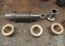
On the 10ee these are not holding the worm gear directly, as they may on some larger lathes. In essence, Its sort of guiding the feed rod. However the feed rod is holding up the worm gear, which in turn mates with worm wheel.Guys, what should these bushings measure? Need to know if I need to turn new ones.
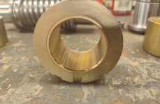
Feed rod is .750, so as you can see, these are really warn. I’ll plan to rebush to .754On the 10ee these are not holding the worm gear directly, as they may on some larger lathes. In essence, Its sort of guiding the feed rod. However the feed rod is holding up the worm gear, which in turn mates with worm wheel.
So you'd like a decent fit to feed rod (the entire length of which may vary slightly). I might aim for a .002" to .003" oil clearance on that bushing to feed rod, checking how it feels the entire length of feed rod.
A little more clearance than that may be ok, but if bushing felt overly sloppy on feed rod, I'd re-bush it. In part because you want good full contact of worm gear to worm wheel. If overly sloppy, worm gear might be forced downward away from worm wheel slightly.
Another fyi, if taper pins hold that in, you may lose a little oil clearance once they are hammered in, so maybe .003" to .004" clearance prior to taper pins.
A little, but not muchBased on the way it works, I would expect the bushing to wear at the bottom, making it egg shaped. Is it out of round?
That makes sense too. I did not have it reground. Maybe I should just leave em?I would be careful here. If the bed and saddle are worn the apron will be lower, so making bushes might cause the carriage to bind.
If you've had a regrind and turcite under the saddle to bring it back up to the original position, yes, make new bushes with a nice running fit.
Incidentally on CVA's the feed rod diameter was increased from 3/4" to 13/16" on later (Mk1a series 3) machines.
Do long bed 10EEs have larger feed rods?
Time has taught me nothing in life is absolutely certainAre you sure the brass bushings are not original?
 , but I'm pretty sure many were one piece originally, though maybe not the case 100% across the board.

Thanks Daryl. Was hoping there was another method besides heat, but it is what it is.I would try to heat the assy. with a blow dryer (propane torch on the bearing if you're going to replace it) and then pound /slam the small end on a solid piece of wood. Try this first before resorting to more aggressive=damaging methods. Maybe alittle Kroil type stuff between the bearing and gear shaft wouldn't hurt.
Notice
This website or its third-party tools process personal data (e.g. browsing data or IP addresses) and use cookies or other identifiers, which are necessary for its functioning and required to achieve the purposes illustrated in the cookie policy. To learn more, please refer to the cookie policy. In case of sale of your personal information, you may opt out by sending us an email via our Contact Us page. To find out more about the categories of personal information collected and the purposes for which such information will be used, please refer to our privacy policy. You accept the use of cookies or other identifiers by closing or dismissing this notice, by scrolling this page, by clicking a link or button or by continuing to browse otherwise.
