What's new
What's new

Curious & curiouser: stout little narrow & broad gauge locomotive

Thanks for the reply asquith, i never knew there was a book about the inchicore works and i must look out for it. I did an interview there years ago, but if you didn't have relatives working there you had little chance of being taken on.
I imagine that you would need a huge amount of turf relative to coal to power a locomotive, its quite a dirty fuel too giving off large amounts of ash.
 
12

JD Guinness08.jpg13 JD Guinness09.jpg14

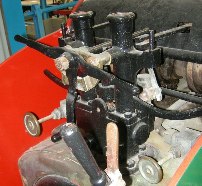
Most of the controls are here. I’m sure there’s a good reason for having three handles on the regulator!

The two vertical pipes will be for the safety valves, presumably Ramsbottom type, and the 'handlebars' will be for lifting the valve spindles to check they’re free.

Behind the safety valves are two horizontal rods, missing their operating levers, which probably pivoted on the studs. I don’t know what they did, perhaps one for the cylinder drain cocks, one for the steam brake? Handwheels - I don’t know. Possibly for the blower, and/or injectors?

Reversing lever in foreground.

The steam brake had a single cylinder with two opposed pistons.

JD Guinness05.jpg15

Crosshead etc.
 
Asquith:

During the mid-1960s, I was living and working in Dublin. I spent most of my free time building a steamcar
with a Uniflo engine, doing the machining at Basin Street shops owned by Guinness. The steam tests on the
engine were done at the main Guinness machine shop because they had a 125 psi steam supply. It was
during this time that I got to know some of the engineering staff and I was given access to some of the
early records dealing with some of the steam engines and locomotives used at the brewery. I have copies of
drawings used to construct the first Geoghegan locomotive by Avonside Engine Company.

The engine built by Avonside shows several features that were changed on the Spence built locomotives, the
main item being the vertical connecting rods. The top of the rod is 4-3/4 inches wide and the bottom is 3 inches wide. At each end of the rod, near the bearing seat, the normally 1-1/4 inch thick rod was thinned to a
1/4 inch thick. Mr. Geoghegan was trying to introduce a degree of lateral elasticity. I have never found any
information regarding how well this idea worked, but it wasn't repeated on any of the Geoghegan locomotives
I have had a chance to examine.

Regarding the hauling capacity of the Avonside locomotive, it was capable of hauling a trailing load of 18 long
tons up the 280 yards of 1 in 39 in the Spiral Tunnel. I don't have any notes on the hauling capacity of the Spence locomotives. A note I found said that the Avonside engine's coal bunker held 4cwt (448lbs) of coal, enough to allow it to operate for 24 hours.

The old William Spence Works in Cork Street had about 150,000 square feet under roof. After the shop closed,
Prescott's Dye Works occupied the premises for a number of years.

I was wondering after Ronan mentioned the Bord na Mona turf burning locomotives, if anyone would remember
the Bulleid Turf Burning locomotive. Obiviously, you did. While talking about Irish turf burners, don't forget the
Sentinel turf fired steam waggon.

Since you have been talking about Guinness, don't forget the Coates Brothers' contribution to steam power at
the Brewery and at Jameson's Distillery.

Hendeyman
 
Last edited:
Hendeyman,

I was hoping you’d join in, knowing your connection with Dublin engineering.

Thanks for the information. I have some questions:

I’ve seen some drawings from an 1888 IMechE paper on Mr Geoghegan’s locomotive, and this shows some minor differences from the 1920 model. They show some sort of box within the firebox, whose role isn’t apparent to me. It seems to be connected to the firebars. Watercooled firebars? Any ideas?

I came across a forum with posts from a young student who was a volunteer at Amberley, and set about cosmetically restoring their locomotive. He comes across as thorough, enthusiastic, and a good communicator. I hope he’ll go far. The thread:-

My biggest task yet...

About 1/3 of the way through, there’s a photo of the loco's motion. At the left, centre, is the throttle valve, and below that there's a three way valve operated by one of the rods I mentioned earlier. Is this for the steam brake? The brake’s cylinder will need an inlet and exhaust. Is there also a permanent bleed to drain off condensate?

The 1888 drawing indicates that the front piston of the steam brake acts directly on the brake arm at the rear of the front wheels, and pulls, by levers, on the rear brake of the rear wheel, if you see what I mean. Vice versa for the rear piston.
 
Asquith:

Since I am working from copies of the drawings for the prototype engine built by Avonside Engine, I can't com-
ment on the components used on the Spence engines of later dates, but I would think that these first engines
were about the same as the prototype. They had fives years of running the prototype to determine any problems before they decided to build anymore to that design.

Referring to the boiler, the box-like structure is a cast iron bridge wall that is used to lengthen the path of the
combustion gases and introduce additional air for better combustion, which helps to reduce smoke emmisions.
The coal is burned on the fire bars (tubes) in the regular manner with air coming in from the ash pit. If you will
look at the 1888 drawing you have, you may notice that the front end of the tubes (manstand end) are slotted.
This was to allow the tubes to be turned as needed to prevent hot spots and burning out of the tubes. The
cool air was drawn through the tubes to the hollow bridge wall and introduced to the combustion gases through
a perforated plate located at the front of the bridge wall. This plate was designed for easy removal and replace
ment, being held in place by a hook (or hooks) on the plate that engaged with a hook (or hooks) in the bridge
wall. Everything about this Cornish style (also know as a Ramsbottom type) boiler was designed for easy main-
tainance.

I was not able to view all of the pictures posted in the "My biggest task yet" article, so I can't comment about
the three way valve. A cylinder cock or drain valve connection is located in the middle of the brake cylinder. The
valve is located near the top of the manstand and requires the driver to reach down to operate it, which is a
bit awkward while the engine is in motion. The condensate drains out under the engine.

The steam brake cylinder is located between the axles and is parallel to the boiler centerline. It contains two
pistons that are connected by ball joints to a cross head located at each end of the cylinder. The crossheads
have cylindrical bosses that stick out on each end and are connected to brake shoes. Between the brake shoes
and the cross heads, attached to the bosses, are connecting rods made from flat bar stock. These bars are
curved to clear the axles and are attached to the rear brake shoes. When steam is applied to the space between the pistons, the pistons move out and apply brake pressure via the cross heads to the wheel surface
closest to the brake cylinder. The cross heads, when viewed from the side of the engine, may be considered
as right and left hand cross heads, effecting the right and left hand wheels. As the right hand cross head
applies pressure to the left side of the right wheel, the connecting link on the right hand cross head pulls
the left hand brake shoe against the left side of the left wheel. At the same time, the left hand cross head applies pressure to the right side of the left wheel and the connecting link on that cross head applies pressure
to the brake shoe on the right side of the right wheel. Confused? I know I am. Any way, that is how the steam
brake works on the prototype.

In Mr. Ellison's article on the Guinness Brewery Tramways he states the engine #15 was given to the Irish
Steam Preservation Society but he didn't know where the engine was at the time the article was written. As
far as I know it is at the steam museum in Stradbally where they hold the annual steam rally every August.
Until a few years ago it was used to haul passagers at the rally, but has since been retired and replaced by
a different locomotive.

Hendeyman
 
Hendeyman,

Many thanks for the explanation - I'm much obliged.

Your description is clear to me, especially as I have the advantage of the 1888 drawing. For the benefit of others who might be interested in the ‘box’ within the firebox, I’ll try and describe the arrangement, having now understood it from Hendeyman‘s description.

Imagine a thick-walled cast iron box about 6" tall and 1 ft high, standing about 6" away from the tube plate. The tubular firebars, which have entered the firebox just below the firedoor, slope slightly downwards to enter the iron box near the bottom. The rear face of this box is perforated by a series of holes which will admit air, preheated by its passage through the tubes.

The firebox itself is cylindrical, thereby avoiding the need for stays. It occupies just over half the length of the boiler. 64 horizontal tubes go from the firebox to the smoke box.

Unfortunately, I wasn’t aware that there might be anything unusual about the firebox, so didn’t pay any attention, and my photos don’t show anything below the firedoor. I hope that anyone who reads this and might visit the museum will be guided to look further than I did. It’s a vain hope, as I have no evidence to suggest that any museum has benefited from a single extra visit as a result of my posts!

JD Guinness17.jpg
The photo above suggests that the boiler shell has a number of horizontal staybars.

Also note the small lever on the LHS. I don’t know what it's for, but I can imagine the look on the blacksmith’s face when the apprentice was sent back with the first example to have the kink put into it to clear some obstruction.

There is no room for a steam dome, steam being taken from the boiler through a long horizontal internal collector pipe placed close to the top.
 
This thread's not dead, it was just sleeping.

After a span of a couple of decades I made it back to the emerald isle for vacation. High on my list of things to do was to revisit two of the Guinness locomotives, one at the Ulster Transportation Museum and the other at Guinness in Dublin.

The first order of business was to look inside the firebox. The locomotive at the Ulster Museum has its grates missing but the "box" at the front of the firebox in the Avonside drawings appears to have been replaced with a type of refractory material, even showing signs of the cement to hold it in place. The Dublin locomotive still has its grates, which appear to be fairly typical locomotive style drop in types. The firebox also had a tool which looks pretty clearly to be the tool used to remove ash and clinker from the bottom of the firebox.
2022-07-08 15.41.22.jpg2022-07-12 12.07.49.jpg2022-07-12 12.07.05.jpg

I was also interested in the functions of the various controls. The knob to the left of the regulator is for the blower, the valve to right is the steam supply for the rather unusual (at least to me) injector. 2022-07-08 15.41.43.jpg The water is controlled by a valve on at the rear of the right hand water tank. The lever to the left of the regulator, I am fairly sure, is the brake valve 2022-07-08 15.47.43.jpg and to the right is the cylinder cocks.

The lever on the lower left side is for the sanding gear.

One thing I didn't notice is how the cylinders are lubricated. I didn't see any of the usual devices. In other photos I have seen bronze cylindrical objects on top of each cylinder but under the shroud and I don't know if this could be for lubrication.

Roger
 
Last edited:
Roger; I usually get a bit snippy when people exhume long-dead threads, but as you say, this one was but sleeping, and I missed it on its first outing. This is really interesting. I'm a member at Amberley, and will take a much closer interest in this loco when I next visit.
George


Back
Top