What's new
What's new

10EE or CVA Apron Oil Pocket wadding

CarbideTip

Aluminum
Joined
Sep 21, 2016
Location
Woking, Surrey, UK.
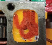
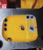
Can anyone tell me what material I should be putting in here:

1659474876515.png

I've searched and seen cotton waste mentioned.
What is the function of this? Flow restriction?

Any help appreciated.
Martin.
 
Can anyone tell me what material I should be putting in here:

View attachment 370601

I've searched and seen cotton waste mentioned.
What is the function of this? Flow restriction?

Any help appreciated.
Martin.
I think it's there for a slow release of oil. Those ports are gravity drain. The string slows the flow and absorbs a little too slowly drip. It also reduces the volume of oil to fill the small sump but I'm not sure that's a reason for it being in there.
Thats my take on the wad of cotton string.
C.T. use cotton string
 
Last edited:
Many times they put oil wicks in oil lines and over here in the states you can buy oil wicks from Hardware Stores. Oil wicks used for kerosene (paraffin) lamps. Old steam engines used oil wicks too. Also I have used the bigger tobacco pipe cleaners or the small ones twisted together and inserted in the holes.. Also we used white felt 1/4" thick cloth pad laid on top of all the pipes. For that many oil lines I would use the oil wicks. You need to clean those pipes out first as they look filthy. https://www.hobbylobby.com/Home-Dec...ies/Replacement-Oil-Lamp-Wicks---1-8"/p/37849 https://www.usplastic.com/catalog/i...A&utm_term=usplastic&utm_content=All Webpages
 
Last edited:
Many times they put oil wicks in oil lines and over here in the states you can buy oil wicks from Hardware Stores. Oil wicks used for kerosene (paraffin) lamps. Old steam engines used oil wicks too. Also I have used the bigger tobacco pipe cleaners or the small ones twisted together and inserted in the holes.. Also we used white felt 1/4" thick cloth pad laid on top of all the pipes. For that many oil lines I would use the oil wicks. You need to clean those pipes out first as they look filthy. https://www.hobbylobby.com/Home-Decor-Frames/Candles-Fragrance/Candle-Accessories/Replacement-Oil-Lamp-Wicks---1-8"/p/37849 https://www.usplastic.com/catalog/item.aspx?itemid=123229&msclkid=ba7ba130845511271840c3dae8fd6ae8&utm_source=bing&utm_medium=cpc&utm_campaign=SB | Dynamic Search | RLSA&utm_term=usplastic&utm_content=All Webpages
What better than a product made to wick oil.
[no affiliation]
The wide flat ones could be used laying in Carbide tips little reservoir and maybe insert about an inch of the small wicks in the link above down the bearing passage.

Under the top of the apron of the American Pacemaker they cut pieces of felt about 2" long and put half down the oil passage going to the bearings and bent the other half over and laid it in the oil passage grove. As with other lathes works as a primitive metering valve. Really not so primitive but do need periodic changing. Not waiting 50 years.
It's not brain surgery but does deserve some careful thought.
 
Last edited:
Thanks for the replies folks.

When the apron came apart there was a congealed mass in that pocket that I discarded without examination. With hindsight I should have studied it!
Sorry, I should also clarify: The picture I posted is from a spare apron that has been cannibalised for parts. The pipes have been cleaned or replaced in the one I’ll be using but I hadn’t got a picture of it handy.

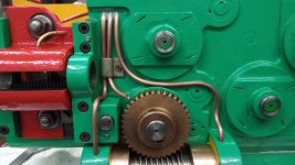
It certainly seems like some sort of metering is required. Trying it on the bench the oil pump delivers a small amount of oil on each stroke, but that disappears down the pipe nearest to the delivery point. Those further away don’t get a look in. I think some experimentation is justified since when its installed on the lathe there’s no easy way to check that oil is getting to where it’s supposed to. On my CVA (English lathe based on the 10EE) there are 7 outlets from this well: long and cross feed clutches, cross feed intermediate gear shaft, half-nuts, worm wheel, left and right worm thrust bearings. These last three are easy to bench check and, as it happens, they are the furthest from the delivery point.

Here’s the refurbished one (in the same orientation as previous):

OilPocket.jpg

and these are the three that will be easiest to check:

WormFeeds.jpg

The list to try so far:

1) Felt. I already have some of that for the way wipers.
2) Pipe cleaners. I wouldn’t have thought of that one!
3) Oil lamp wick material.
4) Worsted wool. (This is used on lots of vintage stuff in the UK and has good capillary action)

I will report back!
Thanks. Martin.
 
CVA's and 10ee's were designed with expectations that it would be used as a production machine. The oiling system being used daily would stay well primed and oil flowing at a very slow rate and keeping things well oiled.

Now they aren't used daily by many of today's owners. If a lathe sits for three weeks that prime of oil is lost through gravity drain. There should still be oil there to get by for a while keeping it lubed.
But if the occasional user does a lot of ocasional work close to the chuck only cranking the carriage within an eight-inch range over many uses the lost prime of the system may seldom completely get full.
The apron bearings, clutches, half nuts and worm gear get gravity fed from the sump shown in this thread.
The carriage gets metered oil covering more distance to get oil all the way up to the cross feed.
If you don't use your lathe daily or weekly or even monthly, consider working your apron handwheel to get some oil pumped up prior to use. Some 10ee's will work the pump oil with turning and the handwheel disengaged and the apron stationary.
Some lathes the carriage has to be moving while turning the handwheel. Like Mine

This is just something to think about. Maybe everyone already does this

I'm going to add manual ball oilers to the top of my carriage arms and cross slide so I can add oil those as I wish.
Also adding a couple mods that Texasgeartrain added to his Monarch.

Carbide Tip
The cavity on your CVA looks like it is smaller than a 10ee. While you're testing your flow would you count how many turns of the handwheel it takes to fill that oil cavity from empty, with the wicking material in it.
It will give you an idea of how to verify a pre prime for the oiling later on.

It's great that you're going to bench test using different materials.
Hopefully you run yours daily with oil flowing and make lots of $Pounds. Not Euro's
 
Last edited:
Carbide Tip...

On the two 10EE’s I’ve worked on (a ’52 and a ’67), both worked off a handwheel and feed rod and deliver a very small volume of oil with each stroke. I believe this is a change from the earlier models which just work off the handwheel. On this apron reservoir, I used squares of felt – pretty much the same as used on way wipers. The more you fill this cavity up with felt, the quicker the oil will fill this cavity, but you need to make sure that you are not creating any dams. It is best to check for this before you button this up. It also changes when you install the check valve.

I believe m-lud is correct about the oil system being designed for more production use. I think it is possible to use the machine briefly over extended intervals and never fully oil the machine. The price we pay for a more automated system.

I have a procedure for starting my machine where I run it at 500 rpm in reverse at a high feed rate with the threading gears engaged as this throws quite a bit of oil in the headstock. I know that I’ve completed my start up when I begin to see the oil level fall in the apron.

The flip side of this kind of oil system is a one-shot system like on my American Pacemaker or Toolmex. These machines get oil there much more quickly, but they waste more oil. Perhaps the one machine in my shop that is in between these two systems in the Pratt & Whitney 12C. It is fully automated but still can deliver oil quickly without too much waste. This system uses a bijur pump that works off the clutch handle, but also uses meter valves and volume rods.
 
As Martin knows, I've not gone into my CVA apron yet but am happily surprised that both ways get oil when the handwheel is turned, almost immediately. My Smart Brown 1024 has an oiler in the apron that will deliver enough oil to the near way but never enough to get over to the far one. I added a ball oiler on the back side of the carriage and into the end of the pipe traveling the length of the cross slide. A few squirts keep the way oiled for several days.

Dave
 
Mike (m-lud), the CVA oil pocket is approximately 1.25” x 1.63” and about 7/32” deep at the deepest point. It looks like it’s just a cast feature. Apart from the pipe holes none of it has been machined. How does that compare with the 10EE?
The pipes are all 5/32” OD and about 3/32” ID.

Trial 1
Over a period of 5 days I tested a piece of 1/8” felt, cut to fit the pocket. I initially soaked the felt with oil, then closed the cavity with a flat piece of steel to represent the underside of the saddle. Over the 5 days I rotated the hand-wheel a total of 1000 times to represent occasional rather than continuous use. At no time did any oil appear at the worm wheel or worm thrust bearing. There was plenty in the half-nut which is the nearest outlet to the pump delivery pipe. I was disappointed with this. I had fully expected the felt to absorb oil until saturated and then for it to ooze out into each of the pipes. From this I have conclude that felt alone would not be suitable.

Felt.jpg


Trial 2
Although I’m not a smoker I have some pipe cleaners as they are useful for cleaning small tubes/holes.

Pipecleaner.jpg

And before someone asks, no it’s not a dead caterpillar!

They appear to be made of two strands of wire twisted together with a coarse helical inclusion of some sort of cotton or synthetic material. I cut some short lengths and poked each end into different delivery pipe. As there are an odd number of pipes the last one was cut a bit shorter and left loose in the pocket.

Pipecleaner2.jpg

I gave the whole mass a squirt from the can and covered the cavity as before. Over the course of a day I cranked the hand-wheel a total of 350 revolutions. After 250 oil appeared at the worm thrust pipe and after another 100 at the worm wheel pipe.

Pipecleaner3.jpg

I have used a piece of paper towel to collect the oil which shows darker in the picture.

(To be continued)
 
Any idea how many turns of the hand-wheel it takes to fill the reservoir?

On my 10EE, I installed a ball-oiler above the reservoir, so that I can manually add oil when the machine has been sitting for a while.

Cal
 
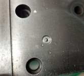
Oh Cal. My saddle was back on with the apron hung but there was a niggle in the back of my mind about putting a ball oiler over that pocket.
Then I read your post .... so it's all off again and onto the mill

Balloiler.jpg

So now mine has a ball oiler too. And yes, as the CVA doesn't pump from the feed shaft I can give it a squirt from the can to get things started.
Thanks for the nudge:)

No, I didn't try to find how many turns were needed to fill the pocket.
I didn't think there was much point since it will start feeding out as soon as there's enough to get to the first outlet pipe.
But it's still on the bench. I could try if you think it would be useful information.

Martin
 
I think that would be interesting to know. If it takes 200 turns to get oil to the point that it's going to feed all the tubes, then you know that, for quick jobs, you need to pre-fill the reservoir via the oil fitting. I would have done it if I had thought that far ahead when I had mine apart.

Cal
I think when monarch designed the lathes, they were expecting that they would run shift work in a production environment. Now many of these lathes are used less often. That reservoir gravity drains while the lathe sits. Add a ball oiler like Cal has on his or a small set screw to remove and fill that reservoir before every use.
It may never get filled and work as intended from just handwheel cam pumping. Especially doing short parts close to the chuck.
This may be the cause of a lot of the apron and carriage wear we see. The carriage oil line bypasses the reservoir but may also lose some prime from sitting. Adding oil ball oilers to the carriage directly above the oil passages to pre prime those would also be good.
When adding oil to the reservoir you need to make sure you're not over filling the apron because overflow will drain back into the main apron sump. Watch the sight glass.
Spinning the handwheel 200 times before use is not practical. We are practical people:soapbox:

Carbide Tip
Thanks for posting your testing
Edit:
Sorry, I think I said this earlier in this thread:willy_nilly:
 
Last edited:
Oil pocket capacity.....
I found some taper pins to plug up all the outlet pipes while this test was performed.

Capacity1.jpg

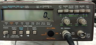
I then set up a counter to automatically count the number of revolutions. This uses something I keep handy – a small piece of stripboard with a Hall effect switch – and put a button magnet on the end of the dial lock screw. Each time the button magnet passes the hall sensor a pulse is produced. This is counted using a standard bit of lab equipment.


Capacity2.jpg

Capacity3.jpg

Then I started turning the handle …….. until

Capacity4.jpg

The meniscus is just about to break. That’s possibly slightly overfull but some of the volume will be taken up by the taper pins bunging up the pipes. So we’ll call it evens.
And the result:

Capacity5.jpg

That’s 1452 revolutions.
Does this help?

When the saddle is connected, some of the oil will go to the ways.
 
Oil pocket capacity.....
...That’s 1452 revolutions.
...
Wow! From that I conclude that any 10EE/CVS that's not in pretty regular use really should have a ball oiler added to jump-start the apron lubrication.

Thanks for taking the time to do that bit of science.

Cal
 
When I had the apron saddle apart on my 1968 and on the 1952 that I worked on, they both had a rocker that worked off both the feed rod and the hand wheel. Was this something they always did? If not, when did it start?

On these two machines when I had them apart, I noticed that if you ran the feed rod at a high feed rate, the reservoir would be filled in about 3 to 4 minutes (but I never put a clock to it.) And of course, the more you fill this reservoir with stuffing, the quicker it fills. Since you can’t see this reservoir when it is all put together, my warmup procedure is to run the machine at about 500 rpm at a high feed rate until the oil level in the sight glass falls. At that point I know that it has filled the reservoir and is oiling. Does anyone else use a startup procedure?

I also like the ball oiler idea. It’s simple – which is always a good thing.
 
On round-dial 10EEs there's only one cam that works the pump and it's on the hand-wheel shaft. I think that CVAs are the same. Square-dial 10EEs, like both of yours, have a second cam that works the pump any time that the feed-rod is turning AND the feed direction plunger isn't in the middle, threading position.

Cal
 
I can confirm that my CVA only pumps from the apron hand-wheel shaft. Mine was made in 1961, but later ones seem to be the same in this respect.
I'm firmly of the opinion that the Mk1 CVA was very close to the Round Dial 10EE, but thereafter CVA went their own way, and the improvements that Monarch made were never copied into the CVA.
 
Trial 3
This should have been a wick material for oil lamps, but I could not find any small enough to go into the 3/32” bore of the pipe.

Trial 4
I probably ought to say at this point that quite a bit of my spare time from school days to retirement has been devoted to railway preservation in the UK. The use of woollen ‘trimmings’ in the lubrication of locomotives, old machines, stationary engines, etc. is well known, and it’s one of those things that’s easy to dismiss as yesterdays technology without a second thought. The ‘trimming’ material is chosen for its inherent capillary action and this is utilized to draw oil from a reservoir and deliver it to pipe that takes it where it’s needed. The number of strands of wool can be selected for the desired feed rate. What’s perhaps not so obvious is that in a typically very dirty environment, the dirt gets left behind. The wool is providing metering and filtering. In some applications on moving parts the oil in its reservoir can be thrown about and in these instances the trimming can also function as a restriction, limiting the flow to that feeding through the woollen part.

In this application the feeding and restriction properties are needed. Hopefully the filtering will not be!

This sequence shows how the ‘Plug & Tail’ trimming was made. I used 24SWG tinned copper wire and Worsted wool, but I think a small oil lamp wick or other material would probably work.

CompositeTrim.jpg

Using the loop, the trimming is pushed into the feed pipe leaving the tails in the oil pocket.

InSitu.jpg

This arrangement was tested in the same way. I gave a squirt of oil from the can to wet the wool and covered the cavity. Then as before a sequence of 50 turns, check, wait and repeat until after 250 turns oil appeared at the thrust bearing pipe and after another 100 revolutions at the worm wheel. These are the same numbers as I got with pipe cleaners so either of the two would do. I have chosen to go with the wool.


Back
Top