What's new
What's new

10EE Apron Removal Jammed Half Nuts and Feed Direction Plunger

Donn

Aluminum
Joined
Mar 4, 2009
Location
Northern New Jersey
Starting to go through this new to me '46 square dial and found some issues with the carriage. The apron controls were very stiff and I was unable to raise the half nut lever or move the feed direction plunger. I dreaded removing the apron because this machine has a turret tailstock and I thought that might make it a more difficult job. After reading as many threads as I could find I decided to go for it.
The taper pin on the lead screw came right out and I was happy to find the screw pulled right out the end of the tailstock gearbox after removing the bearing support block.
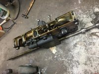
The feed rod was a nightmare. I'm guessing the pin which holds the clutch housing must be either offset slightly or damaged because it was not coming out no matter what I tried. Then the four small allen bolts began to round off. I was able to use a sharp hex key wedged against the gearbox housing to break them loose. They were surprisingly tight. Not being able to pull the rod out of the carriage, I had to take it off in one piece. Fortunately, I was able to slide the tailstock way back off the bed. Just enough to clear the rod.
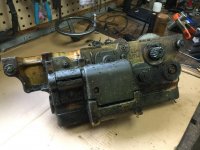
IMG_0001.jpg IMG_0002.jpg IMG_0004.jpg IMG_0007.jpg
 
Hello Donn
Nice write up so far. Regarding the half nuts and feed reverse plunger: I pulled the half nuts and plunger very carefully, clean off the the dirt and grease, use a file carefully on any rough edges where any two parts fit together, spread oil liberally before reassembly. Put back together in the exact reverse order you removed the parts. Test the mechanics: the half nuts and plunger should operate very smoothly.

Now is the time to test the oil pump and consider replacing bearings and Bijur meters if needed. There are many great threads on these subjects if you look under the search key. One additional piece I’d advise: when taking things apart on a Monarch, before forcing anything apart, look for hidden set screws and “c” clips. You will find in your readings others on PM will give the exact suggestion, based on personal experience. On You Tube, Four Ponds has about 30 or so videos on his channel about restoring his square dial. I believe videos 12,13,14 refer to his rebuild of the carriage

Please keep us update with your progress

Jim Murphy
 
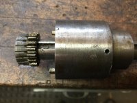
Well, it turns out a good cleaning and lubrication of the half nut slides did the trick. I thoroughly cleaned the whole thing inside and out and tested the pump which is fine. Almost no visible wear on the bronze gear which drives the worm or anything else in there. Just dirty. I am some what confused about the two holes on the clutch housing. I thought they were pin holes but maybe not since the small gear is pinned anyway. No wonder I couldn't get it out. Anyway it's going back together just fine. Thanks for the advice.

IMG_0013.jpg IMG_0011.jpg
 
...I am some what confused about the two holes on the clutch housing. I thought they were pin holes but maybe not since the small gear is pinned anyway. No wonder I couldn't get it out. Anyway it's going back together just fine. Thanks for the advice.

View attachment 345784
The hole in the shell may be related to the setscrew that you see sheared off near the external spline. (At least that what it's for on my '43 round-dial, which has a different type of clutch: link) You need to align the witness marks on the end of the shell with the mating flange on the gearbox output shaft when you reassemble. The witness marks are a 'C' on the collar and a backwards 'C' on the shell; they form an oval (or sideways number '0') when aligned. Square-dial parts sheet 136 shows the type of clutch that you have. There should be a spring between the end of the leadscrew and the gearbox shaft flange. There's also a lengthy discussion of the clutch and a nice diagram in this thread: Feed rod drive mismatch

Cal
 
I have read through related threads and believe I have a grasp on the inner workings of the clutch. I have reassembled the body making sure the pins aligned and witness marks are correct. I'm not sure if that is a broken setscrew or just damage from me trying to drive out an imaginary pin. I still don't know the purpose of the two holes. They are exactly 180 deg apart which is why I thought there must be a pin which needed removal. They extend into the bronze bushing so perhaps they are for lubrication.


Back
Top