What's new
What's new

10EE electric carriage drive?

Andy FitzGibbon

Diamond
Joined
Sep 5, 2005
Location
Elkins WV
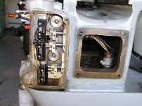
In my project to familiarize myself with the 10EE, I've looked at a lot of internet photos of them. This one (which HGR sold a while ago) has a small casting on the tailstock end of the bed I havent seen before, which looks like it might be some sort of auxiliary feed rod drive. Anyone know what it is, or if it's factory? Just curious.

Thanks,
Andy

Screenshot_20230228-125229_Chrome.jpg20230228_144225.jpgScreenshot_20230228-125210_Chrome.jpgScreenshot_20230228-125118_Chrome.jpg
 
Just bumping this... still curious.
It may be some type of tachometer. at the slow speed you may call it a rotation counter.
Edit: Wire isnt connected!
I can't think of why you would need to know why to keep track of feed rod rotation unless a consistaent stopping point for boring. That can be done with a carriage stop.
It looks more like a sending device than a drive motor.
The wire looks to small to support a drive motor.
My wacky thoughts this morning.
 
Last edited:
Does it drive that shaft on the back side of the bed above the pan?
Is there a pump under the plate.
The Wire isnt connected.

Edit
That looks like conduit
Remove the cover and look at it
 
Last edited:
Wild guess, but something left over from a mechanical tracer attachment would be my guess.
My 612 had a plate and some partial hardware there, it had been originally an electronic tracer machine.
 
Just thinking aloud, I have never seen this attachment:

This was probably a WIAD machine. If you think about what kind of accessories Monarch designed in those days, it brings up both VSR and possibly CSS (although I have only seen CSS on modulars, the design would have worked equally well on WIAD). Both VSR and CSS used an extra pot to control the spindle speed. So I would not expect this attachment to be terribly exotic for a 1951 machine (like an encoder). More likely a limit switch or a pot. So what could they do with an accessory like that? Stop the spindle at a specific point in the feed? Reduce speed as the feed advanced? The latter might make sense for the cross feed, perhaps an early form of CSS. If so, it differed from the later version by not having a mechanical ramp to control the pot.
 
Last edited:
Just thinking aloud, I have never seen this attachment:

This was probably a WIAD machine. If you think about what kind of accessories Monarch designed in those days, it brings up both VSR and possibly CSS (although I have only seen CSS on modulars, the design would have worked equally well on WIAD). Both VSR and CSS used an extra pot to control the spindle speed. So I would not expect this attachment to be terribly exotic for a 1951 machine (like an encoder). More likely a limit switch or a pot. So what could they do with an accessory like that? Stop the spindle at a specific point in the feed? Reduce speed as the feed advanced? The latter might make sense for the cross feed, perhaps an early form of CSS. If so, it differed from the later version by not having a mechanical ramp to control the pot.
While a digital encoder would have been out of the question a tacho/genn type encoder would have been widely in use.
 
Dave, I don't think it was a WiaD machine; I don't see the round cover for the fan on the back of the base.

I also notice that it has another unusual box on the back of the saddle, at the end of the cross-feed screw, where the taper attachment mounts:
20230228_144225-jpg.389076

That suggests an electric taper function, as rabler suggested, however I don't see any wiring coming from the box to support that idea. Another thing that argues against that is the lack of any additional controls or electrical enclosure to support an electric taper or feed mechanism.

I don't have a good photo of the cavity behind the square plate on the end of the bed, but there's a lot of space back there. Easily enough for a motor:
07. Square dial ELSR wiring.jpg
photo by DaveE907​

The square hole and cover on the end of the bed seems like overkill just to access the ELSR wiring. It's more likely that it was put there to allow for some sort of accessory to be mounted inside the end of the bed. As far as wiring goes, cables can be routed through the bed or down into the base.

Anyway, this is an interesting machine!
 
Cal, I don’t see another box at the end of the cross slide. I see a chip shield, and the cross slide has both a top dovetail slide for a rear toolpost slot and a dovetail slide on the side. The side dovetail slides were used for both the cross feed dial indicator and the CSS ramp that was part of the later system.

However, you may be right about having a drive motor in the bed cavity. Monarch had several drive motor feed systems for 10EE on MFG lathes. I used to have a mfg. lathe that had a drive motor at the gearbox end, and I had another that only had a rheostat at the gearbox end.
 
Last edited:
Is that odd box integral with the cavity cover plate? It seems that it could be some standard box bolted to the cover plate. The picture is not zoomed in enough to see for sure.
I have been considering putting a motor in that cavity and having it drive the lead screw. I would use the Clough42 ELS board, so I could do metric threading.
 
From the 'look' of it my guess is an encoder housing. For what?

Is that odd box integral with the cavity cover plate? It seems that it could be some standard box bolted to the cover plate. The picture is not zoomed in enough to see for sure.
I have been considering putting a motor in that cavity and having it drive the lead screw. I would use the Clough42 ELS board, so I could do metric threading.
I think thats an excellent idea. I dont know how you would tune the potentiometer in to cut different threads. It would need a tachometer.

Explain what the Clough42 ELS does.?
Edit: I googled it. Thats Cool. You have it under control

I'm wondering if a small hydraulic motor wouldnt give better control under high torque.
Cutting threads isnt necessarily high torque but you couldnt have speed fluctuations.
Doing anything like this outside of normal gear driven operation may give you a lesson in futility. It may be easy to work out.
Mr CNC
I'm sure you have all this worked out.
Just some thoughts
I like your idea.
If you get it all worked out and could make them as a unit you may have a sellable product.
 
Last edited:
When I bought my 10ee I took a lot of it apart and cleaned out the 60 years of chips and dried oil. While I had the lead screw out, I machined a notch in the end of the shaft and put a bolthole in. This will allow me to extend the lead screw a few inches. I will be able to mount a timing pulley to drive the lead screw. I can mount a motor in the hole under the tail stock. I will have a cover somewhat like the one on the pictured lathe.
That is the idea, anyway. I am going to jump on it as soon as I have time ;)
 
Thanks for the replies... interesting ideas. To be clear, I don't own this. I just pulled the photos off HGR's sold listings. It's a 1951 M-G machine. Here are a couple more photos that may help. I suppose I could call Monarch and see if any special equipment is listed on the build sheet.

Screenshot_20230613-072742_Chrome.jpgScreenshot_20230613-072800_Chrome.jpg
 
That box does look like it is integral with the cover over the end of the main bed casting. It does not look like the drive shaft engages with this mystery box.
 
That box does look like it is integral with the cover over the end of the main bed casting. It does not look like the drive shaft engages with this mystery box.
Screenshot_20230613-072742_Chrome (5).jpg
As said this corner it looks like the cover plate is one piece with the extension for the box. Then the box bolts on.
It's hard to see if the shaft is connected.


Back
Top