How to install the app on iOS
Follow along with the video below to see how to install our site as a web app on your home screen.
Note: This feature may not be available in some browsers.
Largest Manufacturing Technology Community on the Web
Stay Connected:
You are using an out of date browser. It may not display this or other websites correctly.
You should upgrade or use an alternative browser.
You should upgrade or use an alternative browser.
1945-46 Brown & Sharpe No.1 Universal grinder #5426
- Thread starter Elam Works
- Start date
- Replies 62
- Views 24,772

Elam Works
Aluminum
- Joined
- Oct 8, 2007
- Location
- Pennsylvania, USA
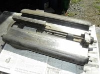
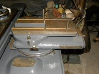
Continuing along with the wheel head slide assembly.
First pic shows the underside of the upper portion of the slide. The feed is via the rack, not the screw. More about that screw in a future instalment. I know, the suspense is terrible!
Next view shows the lower portion of the wheel head slide, and the pinion that engages the rack. The oil gutter has now been install along with the wick that picks up oil and transfers it to the depression around the pinion. It drips down through the hole and lubricates the pinion shaft bearings.
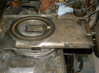
View three is a general view from the side showing the upper and lower wheel head slides assembled.
Fourth view is from the front. Yet to be installed is the front cover. Part of the flat horizontal surface remains exposed, and we are thinking of a neoprene sheet to act as a cover. The surface does not do anything, but stopping any grunge from working its way back under the slide cannot be a bad practice.
Fifth view looking down through the window at the rack and pinion. This does get oil lubrication, but a little sticky grease cannot hurt.
-Doug
First pic shows the underside of the upper portion of the slide. The feed is via the rack, not the screw. More about that screw in a future instalment. I know, the suspense is terrible!
Next view shows the lower portion of the wheel head slide, and the pinion that engages the rack. The oil gutter has now been install along with the wick that picks up oil and transfers it to the depression around the pinion. It drips down through the hole and lubricates the pinion shaft bearings.
View three is a general view from the side showing the upper and lower wheel head slides assembled.
Fourth view is from the front. Yet to be installed is the front cover. Part of the flat horizontal surface remains exposed, and we are thinking of a neoprene sheet to act as a cover. The surface does not do anything, but stopping any grunge from working its way back under the slide cannot be a bad practice.
Fifth view looking down through the window at the rack and pinion. This does get oil lubrication, but a little sticky grease cannot hurt.
-Doug
Attachments


Elam Works
Aluminum
- Joined
- Oct 8, 2007
- Location
- Pennsylvania, USA
This installment will deal with backlash. The feed for the wheel head slide is by rack and pinion, which is bound to have some backlash. The are numerous ways to take the backlash out of such a mechanism, but B&S chose gravity. A counterweight in the lower base and chain keeps the rack firmly against the pinion.
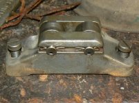
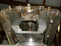
First view is up the arse end from the back. Here you can see a screw and its drive square. By the way we are missing the hand crank if anyone has one. When using the internal grinding attachment, you grind on the rear side of the wheel and the pull of the counterweight needs to change direction; and back again when you are external grinding. Turning the screw all the way from one extreme to the other changes the direction the force of the counterweight is applied to the slide.
Second view is the roller block the counterweight chain runs over. It is a little easer to visualize before installing. note grooves cut in undersides on the roller axles.
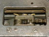
Third view is the roller block installed. The counterweight chain is in place and over the right-hand (rear) roller, pulling the slide forward. Running the screw to the other extreme will cause the chain to drape over the left-hand (fore) roller and pull the slide rearward. The wicks pick up oil from the gutter seen in the last post and deliver to the roller axles.
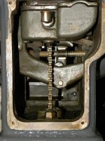
Fourth view. The chain passes down through the hollow pinion shaft and into the lower base where the counterweight lurks.
More on oiling in the next installment, stay tuned!
-Doug
First view is up the arse end from the back. Here you can see a screw and its drive square. By the way we are missing the hand crank if anyone has one. When using the internal grinding attachment, you grind on the rear side of the wheel and the pull of the counterweight needs to change direction; and back again when you are external grinding. Turning the screw all the way from one extreme to the other changes the direction the force of the counterweight is applied to the slide.
Second view is the roller block the counterweight chain runs over. It is a little easer to visualize before installing. note grooves cut in undersides on the roller axles.
Third view is the roller block installed. The counterweight chain is in place and over the right-hand (rear) roller, pulling the slide forward. Running the screw to the other extreme will cause the chain to drape over the left-hand (fore) roller and pull the slide rearward. The wicks pick up oil from the gutter seen in the last post and deliver to the roller axles.
Fourth view. The chain passes down through the hollow pinion shaft and into the lower base where the counterweight lurks.
More on oiling in the next installment, stay tuned!
-Doug
Attachments
Elam Works
Aluminum
- Joined
- Oct 8, 2007
- Location
- Pennsylvania, USA
Not all pipe cleaners are created equal, as can be see in the first picture. A test of the oil capillary action of various brands. It seems pipe cleaners are like machine tools, they don't make them like they use to. Even ones labeled 'super absorbent' do not wick oil very well. Too much nylon or polyester. The grungy one is an original pipe cleaner. It was so filthy it no longer wicked very well either. The one in the center is actually not a pipe cleaner but 1/8 diameter felt, and it sucked up the oil like a wino with a bottle of cheap vodka.
So the felt won out. Fortunately none of the wicks require the formability of the wire core. Second picture is the oil manifold that sits over the roller block mentioned in the last post. There is a well on the left that forms a pond of oil that the tails of the wick lay in. See second pic.
This is not the end of discussion on oiling, but is a convenient point to break as the next post deals with the table.
-Doug
Attachments

Elam Works
Aluminum
- Joined
- Oct 8, 2007
- Location
- Pennsylvania, USA
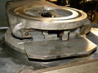
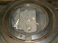
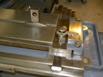
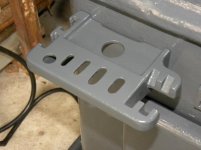
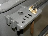
The table is oiled by spring loaded rollers sitting in individual pockets in the lower ways. (First pic) These pick up oil and apply it to the underside of the table.
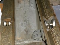
To fill the wells is a little involved. Four threaded plugs have to be removed from the top surface of the table. One is seen in the second pic. The table has to be parked so the holes are over the pockets containing the rollers, and then the oil can be poured through the thickness of the table.
Speaking of the table, that went back on too, third pic. On the No.1, the table and covers are all one casting. Houston, the table has landed, in image four. Two people could manage this, but easier to set it down gently with a chain fall. Easier on the iron, easier on the back. Yet to be placed is the top, swivel table.
While you were distracted by the intricate (and scholarly) description of the oiling system in the previous posts the base got painted. Yet to be done is to pick out the name in white. Gold leaf might be a bit pretentious and it was built under the Wartime Fish Act.
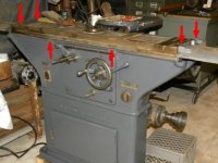
In the last picture, the locations of the threaded plugs and the pockets in the base are indicated by arrows. As you can see, you cannot simply park the table in one location and do all of the oiling. You have to wind the table to one end, and then the other. If only it had one shot central lubrication...
-Doug
To fill the wells is a little involved. Four threaded plugs have to be removed from the top surface of the table. One is seen in the second pic. The table has to be parked so the holes are over the pockets containing the rollers, and then the oil can be poured through the thickness of the table.
Speaking of the table, that went back on too, third pic. On the No.1, the table and covers are all one casting. Houston, the table has landed, in image four. Two people could manage this, but easier to set it down gently with a chain fall. Easier on the iron, easier on the back. Yet to be placed is the top, swivel table.
While you were distracted by the intricate (and scholarly) description of the oiling system in the previous posts the base got painted. Yet to be done is to pick out the name in white. Gold leaf might be a bit pretentious and it was built under the Wartime Fish Act.
In the last picture, the locations of the threaded plugs and the pockets in the base are indicated by arrows. As you can see, you cannot simply park the table in one location and do all of the oiling. You have to wind the table to one end, and then the other. If only it had one shot central lubrication...
-Doug
Attachments

Elam Works
Aluminum
- Joined
- Oct 8, 2007
- Location
- Pennsylvania, USA
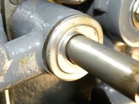
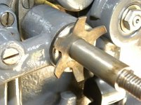
First pic is the center bearing for the top, swivel table. The arrangement is a bit curious. At first it was thought the outer diameter of the bronze sleeve might have a shallow taper and drawing it down into the socket would collapse the sleeve. Not so, the o.d. is cylindrical and there is no means to draw it in further. What were thought to be the tail ends of screws are simply dowel pins. Current thought is that the sleeve is intended to be a slight interference fit and the split with one end pinned is to allow it to spring open slightly to be a snug fit on the pivot post. The cheese head screw to the right secures the table rack underneath.
In the second picture the top of the table has been cleaned and painted where appropriate, and the top swivel table installed. It was indeed a snug fit in the bronze sleeve and required some working back and forth to ease it down into position. There is no way to oil the central pivot beyond whatever lubrication is applied during assembly. But then again it only pivots a few degrees and probably very rarely at that. The anchor for the tail stock is installed, as it cannot be slid in position after the swivel table clamps are in place. Just off the end of the swivel table can be seen two of the plugs that are used to fill the table way wells with oil.
In the third pic can be seen the very nicely engraved plate to indicate the angle of the swivel table. Only missing radians and gradians!
The pool of oil in the wheel head slide is filled by an oil cup on the side. Here in pic four installed and oiling various points. There are a lot of oil cups on this grinder; all over, and in some obscure, hidden places up under the back. I suspect a lot of them tended to get overlooked.
Last picture for today, the cover for the front of the wheel head slide. There is actually about an 1/8 inch gap between the surface and the slide, but a wiper shoves the worst of any accumulation out of the way. It had a strip of leather behind the angle iron that way a bit past it, which was replaced by a strip of neoprene. At each end the cover is held on to the slide with a cheese head screw. I have added an arrow pointing to one of them, as of course there is a story associated with it. One of these screws had half the head broken off. In trying to tap the screw head around with a small pin punch, the remaining half broke off. The screw had developed cracks from the bottom of the screw driver slot. Fast forward a few weeks and time to reassemble. My brother picked out two Allen screws to replace the cheese head screws. I derided this choice as not in keeping with the period of the machine. I was told to go do something anatomically impossible. However I had the last laugh as the original screws turned out to be a bastard 5/16-20 thread! So a copy of the remaining screw was made and the integrity of the machine preserved.
Next is to finish cleaning and painting all the levers, links, ratchets and paws that make up the automatic cross feed that adorns the front cover.
-Doug
Attachments


Elam Works
Aluminum
- Joined
- Oct 8, 2007
- Location
- Pennsylvania, USA
So step back one post and remember how I said the post for the swivel table was a very snug fit and there was no means of adjusting it even though it was split and seemed as if it ought to be possible? Well it is adjustable. In the first picture can be seen a (overlooked) slotted grub screw on the front face of the table. This pushes on a rod that extends to the split bush. There it bears upon the free end of the bush. The second pic shows the basic idea.
Beyond that, the myriad of links and do-dads on the front cover have been disassembled, cleaned, and painted. In the third picture it can be assembled on the front cover. All this stuff was already off the machine when we got it, but it was not too difficult to figure out where it all went by looking at pictures on the internet and in the handbook.
-Doug
Attachments


Elam Works
Aluminum
- Joined
- Oct 8, 2007
- Location
- Pennsylvania, USA
Now, a bit of a mystery in two parts. The grinder came with a coffee tin of smaller washers, bolts, and miscellaneous bits. Unlike the larger castings it is not always apparent where some of this stuff goes. Case in point is the order of assembly of the washers on the worm shaft and the hand wheel. Some of these components are shown in the illustrated parts list in the order they are assembled. Or maybe not!
First picture shows the field of battle.
In the tin of bits was a washer with a peg (picture 2). This seems to fit over the worm shaft and against the paw lever (#104). There is a small hole to accept the peg (third picture). The washer provides a shoulder to keep the paw lever on its journal. So far, so good, the washer is installed in the fourth picture, but not pushed home because the peg is bent. The front face of this pegged washer (#1073) is horribly worn. Both the step (is it supposed to be there or is it wear) and the bore are elliptical shaped.
So mystery number one has resolved itself. Mystery number two is not so easy, and perhaps another B&S Universal owner can assist. See next instalment.
-Doug
Attachments


Last edited:
Elam Works
Aluminum
- Joined
- Oct 8, 2007
- Location
- Pennsylvania, USA
The next mystery is the mystery of the star washer. There is a star washer. It was a lovely little star washer. The problem was the star washer was lost and could not find its home... It does belong to the machine, and is listed as part #153. The question is does it go behind or in front of the hand wheel.
The first picture shows it installed to be behind the hand wheel. This is a good spot in that there is a appreciable gap between the hand wheel and the pegged washer in the last post that needs filling. The second picture shows the washer against the back side of the hand wheel assembly. It is actually the back face of the cross feed dial (#105) There is a counterbore that the petals of the spring span. So what is not to like about this?
Well, a few things actually. A similar #1 Universal from 1948 that we inspected had the star washer in front of the hand wheel. However this machine is missing other pieces in the automatic cross feed and it is not certain it was reassembled correctly. It might not be a good example to go by. A more compelling reason is the 1930 and the 1944 parts list imply that the spring washer goes in front of the hand wheel. It is suggested by the order of washers next to the shaft in the 1930 parts list, but it is shown even more strongly in the 1944 parts list as it is placed immediately adjacent to the front side of the hand wheel.
At first this did not make sense, as there is a nut and a large plain washer that pulls up hard against a shoulder on the cross feed shaft. The spring did not seem to have a part to play in that. Second, the hand wheel was a snug fit on the shaft initially so it did not seem to have a function of floating on the shaft. This was an error of our own making as we had to supply a missing key and probably made it too snug a fit. Without the key the hand wheel does slide axially on the shaft.
So picture three and four shown what the washer would look like in the recess in the front of the hand wheel and then the spring, washer and nut on the shaft (without the hand wheel blocking the view of the shaft.) There are no chafe marks on the face of the counterbore indicating the spring washer resided here (or the washer or anywhere else that I can see), but this seems the logical place; as if the counterbore was made to fit it. Yes the large washer fits the counterbore, but a small washer would have held the hand wheel onto the shaft equally well if that was all that was required. So now we are leaning towards this solution. The only fly in the ointment is it shoves the hand wheel to the rear, and it hits and interferes with parts of the feed paw (#104). Either there is another washer next to the pegged washer at the rear to pad the assembly forward (none indicated in the parts list), or the pegged washer was originally much thicker than it is now.
So the question is, does anyone have 1940s era B&S Universal grinder that they could check the location of the star washer, and measure the thickness of the pegged washer (or combination of any adjacent washers)? In this regard a Number 1, 2, 3, or 4 machine would be identical. It only requires removing the nut holding the hand wheel on, and sliding the hand wheel/dial assembly off.
-Doug
Attachments


texasgeartrain
Titanium
- Joined
- Feb 23, 2016
- Location
- Houston, TX
Your mystery from 2 posts ago,#28, with the pegged washer, and the star washer go hand in hand I believe.
I'm 99% sure that star washer is a lock washer for nut. Once nut is tightened to appropriate thrust between hand wheel, and lever arm, then you bend one of the stars pedals on to a flat of the nut, one of the 6 sides, in other words. Pedals unbent, should point out toward nut. Typically that style would need to grab something on wheel side too, like a notch or something. tapping one pedal into wheel notch, bent one over nut. . . like that. Though I don't see a notch in hand wheel.
The pegged washer is a thrust washer of sorts. Again your going to tighten handwheel nut so you have maybe .002" or something, between hand wheel, washer and lever. I would try going as tight as possible while all can move free. Low clearance to keep dirt out, but free enough so everything moves freely, guessing .002".
You guys are doing an awesome job, btw. I love this machine. I've seen a #2 universal B & S from the same time period I really want to get my hands on.
texasgeartrain
Titanium
- Joined
- Feb 23, 2016
- Location
- Houston, TX
If the star washer is a spring washer, you may need the hand wheel to move freely on shaft. Bringing spring tension to push hand wheel to contact, but don't wail down on nut, so that hand wheel wont lock up tight on lever. just some springy action. May need to loktite nut.
If you take key out for hand wheel does hand wheel slide freely on shaft ? If it does you probably have to dress that key way up a bit.
If you take key out for hand wheel does hand wheel slide freely on shaft ? If it does you probably have to dress that key way up a bit.
Elam Works
Aluminum
- Joined
- Oct 8, 2007
- Location
- Pennsylvania, USA
The star washer is a spring washer, made out of spring steel. Or something that is springy. Tab washers are malleable, and beside would need something on the i.d. to stop the washer from turning on the shaft.
As I mentioned previously, without the key the hand wheel assembly does slide along the shaft.
Having slept on the problem, the more I think on it, the more I believe the star washer does belong on the outer side of the hand wheel. This shoves the hand wheel assembly back against the pegged washer. The pegged washer needs to be of sufficient thickness so that the feed dial does not rub on the paw lever. The pegged washer on the brother's machine is probably worn down in this respect. The thickness is likely not critical, it just has to be enough so the dial clears. So having someone disassembly their B&S universal is not really needed.
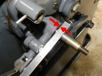
Just need to put a straight edge across from the feed paw as shown in the first picture and figure out how thick the washer needs to be, allowing for the recess in the back of the dial. Then add a smidgen for clearance. This would be an imperial smidgen, since the machine is pre-metrification...
The second picture shows basically what is happening now. Though the pegged washer is not installed in this view, it still is not thick enough to prevent the back of the dial rubbing on the paw lever.
Now why have a star washer? The worm shaft is fixed accurately at the other end with a angular contact ball bearing next to the worm. So the shaft does not float, nor have any end play that needs to be dealt with. However there is a tremendous tolerance stack up from where the worm gearbox is attached at the rear of the machine, to where the front cover and all the bits attached to it at the front are. The worm shafts are all the same length (within minor production tolerances). So there is going to be variation as to how much the worm shaft protrudes from the front cover from machine to machine. This means there needs to be shims or some form of adjustment to have the hand wheel - and more importantly the feed dial - fall in the correct place. I think B&S choose a simpler solution. Fix a shoulder on the front cover to control the proper location and spring load the hand wheel assembly against it. I think this is the most logical explanation.
-Doug
As I mentioned previously, without the key the hand wheel assembly does slide along the shaft.
Having slept on the problem, the more I think on it, the more I believe the star washer does belong on the outer side of the hand wheel. This shoves the hand wheel assembly back against the pegged washer. The pegged washer needs to be of sufficient thickness so that the feed dial does not rub on the paw lever. The pegged washer on the brother's machine is probably worn down in this respect. The thickness is likely not critical, it just has to be enough so the dial clears. So having someone disassembly their B&S universal is not really needed.
Just need to put a straight edge across from the feed paw as shown in the first picture and figure out how thick the washer needs to be, allowing for the recess in the back of the dial. Then add a smidgen for clearance. This would be an imperial smidgen, since the machine is pre-metrification...
The second picture shows basically what is happening now. Though the pegged washer is not installed in this view, it still is not thick enough to prevent the back of the dial rubbing on the paw lever.
Now why have a star washer? The worm shaft is fixed accurately at the other end with a angular contact ball bearing next to the worm. So the shaft does not float, nor have any end play that needs to be dealt with. However there is a tremendous tolerance stack up from where the worm gearbox is attached at the rear of the machine, to where the front cover and all the bits attached to it at the front are. The worm shafts are all the same length (within minor production tolerances). So there is going to be variation as to how much the worm shaft protrudes from the front cover from machine to machine. This means there needs to be shims or some form of adjustment to have the hand wheel - and more importantly the feed dial - fall in the correct place. I think B&S choose a simpler solution. Fix a shoulder on the front cover to control the proper location and spring load the hand wheel assembly against it. I think this is the most logical explanation.
-Doug
Attachments

Last edited:
Elam Works
Aluminum
- Joined
- Oct 8, 2007
- Location
- Pennsylvania, USA
O.k., new peg washer made, hardened, and installed. Spring washer on outboard side of hand wheel and hand wheel assembly installed (picture 1). Optimal thickness of the peg washer is when the feed pawl is aligned with the dial/feel ratchet wheel (picture two).
That settled, a short summary of the automatic cross feed might be in order. Picture three shows the front of the machine. The right-hand adjustable table stop has pushed the cross feed lever (#112) to one side. A close up (picture 4) shows the tail end of the cross feed lever almost against one of the stops on what the book calls the feed roll lever (#47). This is the horizontal lever with the two plungers. Continuing to force the table will cause it to come hard against the stop and will break things, but under normal circumstances the table direction will have reverse by now. But it might explain why sometimes these machines are seen for sale with the roll feed lever broken.
In picture five, the left-hand table stop has knocked the feed lever the opposite way in the direction shown by the arrow. On the roll feed lever are two adjustable plungers. The book calls these feed stop pins (#595) but what they really do is determine how much the cross feed advances (if any) each time the table hits the hits the limit stop and reverses direction. How far the plunger is threaded upwards will determine how far down the roll lever is pushed (arrow) out of the way, and so the stroke of the feed pawl on the far end. (Refer back to picture 1.) This can be set to vary the stroke from one ratchet tooth (notch) to a maximum of sixteen. Each notch equates to 0.00025" on the work diameter. The stop pin on the left is adjusted so the roll feed lever is pushed down and feed pawl grabs a few notches. The stop pin on the right is adjusted too low to contact the feed lever. So in this instance the cross feed only advanced when it hits the right-hand limit of table travel(and the table changes direction), rather than when the table reaches the end of travel in both directions.
If that more than you ever wanted to know, then I won't go into what automatically stops the cross feed when the work reaches the predetermined size!
-Doug
Attachments


Elam Works
Aluminum
- Joined
- Oct 8, 2007
- Location
- Pennsylvania, USA
Taking a break from automatic cross feed, work continues on the wheel head. Picture one shows the compound on the wheel head slide. The wheel head slide can be rotated to any angle and further the wheel head can be independently swiveled.
Note the t-bolts. They are a bastard 1/2-14 thread! So it is important to make sure you get all the hardware with your grinder.
Picture two is the underside of the wheel head spindle stand getting a lick of paint.
Picture three it in turn is mounted on the compound, some painting yet to be done. Also already attached is the motor sub-plate. This is held on by three 9/16-14 bolts! Besides the bastard pitch, one would expect by the time it came to mounting the electric motor they would be up to 3/4 inch bolts! A 3/8-14 thread has also been discovered. I suppose Brown & Sharpe must have only had a set of 14 threads per inch chasers which they cranked in or out depending on what diameter bolt they needed!
The motor sub-plate slide fore and aft on a keel and keyway to tension the belt to the wheel spindle, which will be grasped in the two saddles at the front end (future instalment). The post in the back corner is for a substantial pivoting cast iron belt guard.
Last picture for now is the critical wrench caddie attached to the front of the base. No detail too small to be overlooked in this Concourse d'Elegance restoration! Unfortunately, do not have the full compliment of official Brown & Sharpe wrenches.
-Doug
Attachments


Elam Works
Aluminum
- Joined
- Oct 8, 2007
- Location
- Pennsylvania, USA
In post #33 I described how the cross feed worked. Turns out that was a load of BS, and I don't mean Brown & Sharpe!
While our local turret lathe expert was inspecting the progress this past weekend, trying to work the cross feed as I described was found to be impossible. The roll feed lever is not pushed down by the stop pins. It was recognized all along that that was a rather violent way to deflect the lever; but absence of battering, wear, and tear suggested the action was so slow that it was not as violent as imagined. (As yet the machine is not under power.) What was not realized until playing with it some more is the stop pins are so close together that one has to always be backed off to allow the other to act.
The reality is the stop pins do not deflect the lever down at all. They stop the lever from returning up.
On the back side of the feed roll lever is a free roller on a stud. It is this that strikes a ramp on the tail end of the feed lever. (See first picture.) There is a return spring in a springbox that pulls the roll feed lever to its uppermost position.
A ramp on the bottom of the cross feed lever strikes this roller and pushes the roll feed lever down. (Picture two) This causes the pawl to grab a few notches on the cross feed dial and feed the wheel into the work piece. When the cross feed lever swings out of the way, the spring lifts the roll feed lever. But it can only lift it as far as the stop pins allow. And it is this that determines how much feed it takes. If the stop pins are fully retracted the roll feed lever returns to it uppermost position. On it next downward stroke it can grab a full sixteen notches on the feed dial. If the stop pins are fully extended, the roll feed lever can only return far enough that the pawl can only grab one additional notch (1 notch = 0.00025" on diameter).
I do not seem to be able to go back and edit my post, so adding the correction in this addendum. Oddly, no one called me out on the faux pas. I did get some criticism over the tool caddy and the amount of to-do made over it. So I am including another picture of it!
-Doug
Attachments


johnoder
Diamond
- Joined
- Jul 16, 2004
- Location
- Houston, TX USA

Elam Works
Aluminum
- Joined
- Oct 8, 2007
- Location
- Pennsylvania, USA
John,
Yup, right there on the initial page: "...which acts as a stop to limit the upward throw on lever..." While the 1944 handbook tells you how to use the automatic cross feed, it is more a list of instructions of what to do. Do this, then that, adjust these... without overly explaining how it works. It would have been easier if it was under power, and one was able to watch it in action. Spinning the pulley over by hand at the back while trying to fiddle with all the levers on the front is not the easiest way to enlightenment. If I had been a little more vague I might have gotten away with it but I had to go into excruciating detail...
Small job this episode. One of the parts missing was the stud and graduated nut for adjusting the swivel table angle. An example was borrowed from an 1947 machine. (First picture) This was yet another example of a bastard 1/2-14 thread. At the other end is a 3/8-16 thread, the current National Coarse (NC) default. Yet even that is not to standard. Initially a 3/8 NC bolt was tried in the hole on the brother’s machine and it immediately got tight. This led us to think it was yet another B&S bastard pitch. However when the sample turned up it revealed that the pitch is standard but the pitch diameter is about 0.010 inch undersize.
The 1/2-14 thread was also cut undersized; about 0.012” under. The theoretical pitch diameter should have been 0.452 to 0.447 according to my thread tables, but the sample stud measured 0.437”. I am not really sure what the deal is with the seemingly intentional use of undersized pitch diameters.
The second picture shows the new stud and nut. I don’t think the 14tpi pitch in this case is significant, as in ‘one turn would equate to one degree’ or anything like that. Rather it is a continuation of the theme of using 14tpi found on some other hardware. As the stud and nut were required it could have just as well been made to 1/2-12, but as we had a 1/2-14 tap in the bin of odds and orphans, the peculiar pitch was retained. The use of a tap did mean that the anomaly of the B&S pitch diameter was not retained.
-Doug
Attachments


Jim Christie
Titanium
- Joined
- Mar 14, 2007
- Location
- L'Orignal, Ontario Canada
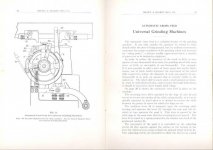
The Grinders described in the link below are older than yours and most of the material may have been covered in other links that have been posted but you may find some more new bits of information there.
Internet Archive: Error
Regards,
Jim
Internet Archive: Error
Regards,
Jim
Elam Works
Aluminum
- Joined
- Oct 8, 2007
- Location
- Pennsylvania, USA
Time for another BS session; BS #5426 that is…
Split the main 3600 rpm 1hp wheel head motor to check out the internal condition. About what you would expect in a seventy-one year old motor. The winding varnish looks a little gooey, but have dealt with that problem before in motors and magnetos. Clean off the decomposed varnish and re-seal with Glyptal.
The bearings are babbitt lined steel sleeves. These feel a little more worn than desirable, so on the lookout for a supply of same. Lacking that I suppose it could be converted to bronze sleeves; or re-cast and bore the babbitt. Have done that with bigger bearings before, but never one this small and the Babbitt so thin. Fortunately the motor shafts look pristine, probably due to the use of babbitt versus bronze.
In the next two pictures notice the very neat pressed cover to blank off the cooling slots. Clearly not a specially built dust-proof motor but a conventional type converted for a grinding environment.
In the last picture is the motor pulley. There is a tapered adaptor that resides on the motor shaft more or less permanently. This can be seen sitting on the pulley to the right. Several sizes of pulleys were available to tailor the wheel speed, and these could be quickly interchanged on the taper. We have only the one set of pulleys, however. The pulley nut is on the left.
-Doug
Attachments


Elam Works
Aluminum
- Joined
- Oct 8, 2007
- Location
- Pennsylvania, USA
While awaiting divine revelation on the wheel motor bearings, an examination of the grinding spindle was made. The spindle is pretty much the heart of the grinder and if it is in poor condition it will show in the finish of the work piece. The spindle felt pretty good, but thick, congealed oil will hide a multitude of mechanical evils! All-in-all it is not that bad, but will need a little reconditioning to make it good as new; and now would be the time to do it.
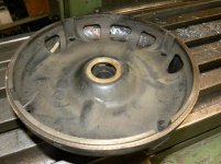
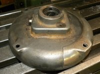
I have to say I am not all that impressed with the spindle design. I do not mean the use of plain bearings, I can accept that as superior for its ability at that time to dampen out vibration given the rigidity of the machine; or more accurately, lack of rigidity. One thing machine tool builders have learned over the decades is in a quality machine, you can never have too much rigidity! No, my criticism is more practical to the general use of the machine. The placing of the main grinding wheel between the bearings (rather than overhung) certainly gives the wheel the best support and evenly distributes the load between both bearings. However it does mean that you have to partially disassemble the spindle to change out the wheel. The same apples if you want to change the spindle pulley for a different diameter (wheel speed). Removing the spindle from the wheel stand is a fairly simple operation (first picture). The clamps roughly match the spherical shape of the housing of the wheel spindle bushing, but only touch at three spherical contact points. Yet this aggravation of dismantling the spindle could have been avoided by using either a stone with a bore larger than the three inch, or change the bearing housing slightly so that the three inch bore could be threaded over it without disturbing it.
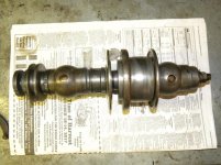
The second picture shows the quickly detachable spindle on the bench, sans-wheel. Perhaps Messrs. Brown & Sharpe expected any Tool Room worthy of the name to keep several assembled spindles on hand configured for different applications. $$$!
The third picture shows the right-hand end of the spindle. Shown from left to right the pulley flange, the wheel spindle bushing, and then the adjustment for the end-float. The larger hex nut at the end of the shaft screws up against a thrust washer to set the correct clearance and the small bolt jams against the end of the shaft and locks the adjustment. The book advises 0.003-0.005 inch clearance cold, which should diminish to 0.001 at operating temperature. Setting of the bearings is very much by feel; the manual says the bearings should be quite warm, but not hot. Not sure if that is in Fahrenheit or Centigrade! This applies to the radial clearance as well, which I will get to anon.
The fourth picture shows the mounting taper and hub (2 inch diameter) for the stone when used on the left-hand end of the spindle. This was not recommended for general use, except in certain circumstances when the wheel head compound was set at an angle and access with the primary wheel was not possible. Another occasion is when sharpening tools and cutters; the normal work head would be removed and a optional universal (work) head substituted on the left-hand end of the table (fifth picture). When using the left hand end of the spindle the wheel was limited to six inch diameter. The primary (central) stone could be up to 10 inch diameter but a mere 1/2 of an inch wide. Normally the hub for the left-hand stone would not be installed unless in use, when not the taper and thread on the spindle would be covered by a protective sleeve. We seem to be missing that ‘hubcap’, but it should not be hard to make a replica. A stone could also be mounted at the right-hand side of the wheel stand of the slightly larger #2, 3, and 4 Universal with the purchase of some optional equipment. The spindle on the #2-4 was more substantial and had vee-belt drive rather than the flat belt retained on the #1.
That is it for the number of attachments allowed, so in the next installment we shall delve into the interior of the spindle. Bet you cannot wait!
-Doug
I have to say I am not all that impressed with the spindle design. I do not mean the use of plain bearings, I can accept that as superior for its ability at that time to dampen out vibration given the rigidity of the machine; or more accurately, lack of rigidity. One thing machine tool builders have learned over the decades is in a quality machine, you can never have too much rigidity! No, my criticism is more practical to the general use of the machine. The placing of the main grinding wheel between the bearings (rather than overhung) certainly gives the wheel the best support and evenly distributes the load between both bearings. However it does mean that you have to partially disassemble the spindle to change out the wheel. The same apples if you want to change the spindle pulley for a different diameter (wheel speed). Removing the spindle from the wheel stand is a fairly simple operation (first picture). The clamps roughly match the spherical shape of the housing of the wheel spindle bushing, but only touch at three spherical contact points. Yet this aggravation of dismantling the spindle could have been avoided by using either a stone with a bore larger than the three inch, or change the bearing housing slightly so that the three inch bore could be threaded over it without disturbing it.
The second picture shows the quickly detachable spindle on the bench, sans-wheel. Perhaps Messrs. Brown & Sharpe expected any Tool Room worthy of the name to keep several assembled spindles on hand configured for different applications. $$$!
The third picture shows the right-hand end of the spindle. Shown from left to right the pulley flange, the wheel spindle bushing, and then the adjustment for the end-float. The larger hex nut at the end of the shaft screws up against a thrust washer to set the correct clearance and the small bolt jams against the end of the shaft and locks the adjustment. The book advises 0.003-0.005 inch clearance cold, which should diminish to 0.001 at operating temperature. Setting of the bearings is very much by feel; the manual says the bearings should be quite warm, but not hot. Not sure if that is in Fahrenheit or Centigrade! This applies to the radial clearance as well, which I will get to anon.
The fourth picture shows the mounting taper and hub (2 inch diameter) for the stone when used on the left-hand end of the spindle. This was not recommended for general use, except in certain circumstances when the wheel head compound was set at an angle and access with the primary wheel was not possible. Another occasion is when sharpening tools and cutters; the normal work head would be removed and a optional universal (work) head substituted on the left-hand end of the table (fifth picture). When using the left hand end of the spindle the wheel was limited to six inch diameter. The primary (central) stone could be up to 10 inch diameter but a mere 1/2 of an inch wide. Normally the hub for the left-hand stone would not be installed unless in use, when not the taper and thread on the spindle would be covered by a protective sleeve. We seem to be missing that ‘hubcap’, but it should not be hard to make a replica. A stone could also be mounted at the right-hand side of the wheel stand of the slightly larger #2, 3, and 4 Universal with the purchase of some optional equipment. The spindle on the #2-4 was more substantial and had vee-belt drive rather than the flat belt retained on the #1.
That is it for the number of attachments allowed, so in the next installment we shall delve into the interior of the spindle. Bet you cannot wait!
-Doug
Attachments


Similar threads
- Replies
- 8
- Views
- 751
- Replies
- 4
- Views
- 160
- Replies
- 15
- Views
- 1K
- Replies
- 29
- Views
- 2K
- Replies
- 15
- Views
- 1K