What's new
What's new

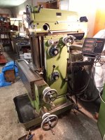
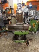
1976 FP3, my new mill

X gib looks like someone went over it using that machine for the first time
Its a used machine yes
I always scrape away that ridge Not usefull perhaps but it makes me feel better:D
For the scales: I have had very few machines with their original scales
And to replace one through its original channels you have to cut the connector off
Fiddle the cable trough the machine Solder the wire in the connection box under the motor and some more fiddling to get it to the readout
So most people put a replacement outside the machine
I have no problems with that
If you want the original brackets I have the one from post 19 laying around somewhere I think
Peter
Hey there Peter, thanks for the reply:

- what do you mean by "
X gib looks like someone went over it using that machine for the first time
Its a used machine yes"?
That someone without scraping experience did that gib? Does scraping look 'non Deckel'?

- What's that ridge that you always scrape out Peter? Do you mean relieving the middle section? You do that by scraping, not milling?

- right on the scales, it takes some effort. At some point I might do it. Good thing is that those connectors are top quality.

- what do you mean by 'original brackets' Peter?

BR,
Thanos
 
Last edited:
Pfff
I was not clear it seems
The scrapping looks bad to me Not done by Deckel IMHO Not functionally bad perhaps but not regular Completly random
With a used machine you can have that Not a big issue

The ridge you see on the right side of that gib (The unworn part )

Original long bracket at that red circle

Peter
Clear now, thanks Peter
 
Not much of an update today:

I took X gib out, seems decent to me:
View attachment 375380
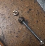
And so are the shims washers for adjusting the X gib:

View attachment 375381 View attachment 375382
I've only, recently, learned about this gib configuration (Ross spent a couple of posts explaining, I had never seen something like this before), but I would assume that the range of adjustment that is shown here must be a good thing, right?

Also, regarding the X slide stops I mentioned earlier.
This is how it is with the FP2:
View attachment 375383
There is that black hex screw with its locknut on the endcap, you adjust it accordingly and you get a nice positive stop when travel is exhausted manually. (trip dogs have done their job 10 mm earlier).

No such thing on the FP3:
View attachment 375384View attachment 375456
View attachment 375385
When end cap (grey part in red circle, top pics) is about to hit the carriage, or screw support is about to hit the oiler mounting screws, motion is stopped by the trip dogs. But the feeling is not positive, you fit the trip dogs a bit, it's not like it actually hits a hard stop. I am talking about MANUALLY moving X, no power feed.

How do your machines stop at the limits of the manual motion along X guys?
Thanks,
thanos
Pretty sure my FP3 travels are controlled via the hard stops. The ones that are doweled in place, not the adjustable trips on top that can be moved.

Agree with Peter that the gib has been "flaked" post factory.
Generally think that the factory used scraping without flaking on the gibs. But to be honest i have seem way more of the factory work on the NC machines, so results may vary.
Cheers Ross
Alright,
based on Peter and Ross, it seems that the X gib has been replaced at some point, that's also why there is so much adjustment left. I am ok with this (I'll check gib fit and adjust if necessary).

Z gib wasn't replaced apparently, took it out yesterday: only around 5mm of adjustment left. Will last me for a long time till I'll need to deal with it.

Thanks for the reply on the X limit-stops Ross. Mine as well stops (via the feed trip lever) on the doweled hard stops, which feels a lot less positive than the actual hard stops (adjusting screw on the end cap hitting the carriage) on the FP2. But I'll have to sort out a travel limit issue with the X scale first and then I'll see what to do with this.

Regarding progress, nothing much to report.
My approach is that I put the mill to work as fast as possible, in order to actually assess it's condition and shortcomings. So, I won't deal with end stops or painting or cable sorting now. I will regrease the spindles though (ordered some LDS 18 from Singer since I don't think I have enough for two spindles) first. I also cleaned the wipers.
They did a great job with the Y wipers.
Not so much with Z, only a rubber wiper on mine, but is has bellows so no big deal.

I also keep on cleaning it a bit so that I can actually touch it (it was that filthy). It's starting to look more like a mill now...:

20220921_234854.jpg

20220921_234916.jpg

20220921_235049.jpg

20220922_231101.jpg

BR,
Thanos
 
I do not think the gib is replaced per se I think it is just scrapped over a bit
While you are at it I would sugjest to lube the point on top of the machine extensivly for a while
I take out the nozzle in general.put a small funnel on and pour oil in
That point is mostly forgotten and it can reduce the soundlevel if lubed this way

Peter
Thanks Peter,

cleaning is over for now. I'll check oils, do as you said with the head lubrication, and put it to work in order to find out if/what needs extra attention.

BR,
Thanos
 
Hi guys,

I am putting the vertical head together and would like some help putting together the large bevel gear assembly:

20220927_232648.jpg

How do you lube these?
Manual says oil vertically through the nipple top front of the head but I think that oil will never reach these bearings here. I think they should be Klubered! What do you suggest?

Thanks
Thanos
 
I would hold on to the manual But perhaps doing both ??

BTW I would bleu one of the bevel gears and see if the set needs adjusting
Adjusting can be needed if it is taken apart by someone and not assembled correctly
I have a Klingelnberg manuel somewhere telling how to do so
It can make a difference in soundlevel
How much sound does it make in Db??
Hey Peter,

thanks for the reply!

Yes, I'll do both. If kluber is needed, nice to have it there. If not, it will wash off with the oil. I think oil is for the quill and bevel gears perhaps.

I know your sensitivity about milling machines sound level, but I can't indulge it at this point. I don't have a proper dB meter (my phone using those apps is no good, mic is semi-dead). All I can say is that, contrary to the seller's statement, it's not louder than the FP2 (with the long reach mind you).
Where do you place your dB meter for the sound measurement in case I can get my hands on one?

BR,
Thanos
 
Soundlevel is just a indication so others know what you are talking about more or less
Checking it is not a great deal
Assemble the gears with on one some spotting ink spread thin
Then let it run for a few seconds on low speed
Then on the other gear you can see where gears touch oneanother
It should be in the middle in both directions
Play between teeth I check with a soldering wire
Roll it in between the teeth and measure the wire
A pdf showing how to adjust

Peter
 

Attachments

  • Klingelnberg engels .pdf
    124 KB · Views: 15
Last edited:
Soundlevel is just a indication so others know what you are talking about more or less
Checking it is not a great deal
Assemble the gears with on one some spotting ink spread thin
Then let it run for a few seconds on low speed
Then on the other gear you can see where gears touch oneanother
It should be in the middle in both directions
Play between teeth I check with a soldering wire
Roll it in between the teeth and measure the wire
A pdf showing how to adjust

Peter
Thanks Peter,

I'll do check the gears for sure.
I am familiar with setting such gear assemblies: I've been messing with BMW motorcycles for ages and they feature a final transmission with similar gears.

Many thanks,
Thanos
 
Hi to all,

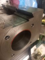
I still haven't been able to clean the horizontal quill lock and restore its smooth operation, so I think I need to remove the front ring-cap on the headstock...

20221004_014310.jpg

I pulled the caps out:

20221004_014740.jpg

Took the 4 M6 screws out and started scratching my head: There is nowhere to push or pull that cap off of in order to remove it.
That's the top part:
20221004_023148.jpg

Any ideas? Has anyone actually removed this?

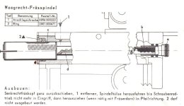
Manual does say: "2 darf nicth ausgebaut werden", but I hope this is not generic but applies to the quill removal instructions. In such 'you must not remove ring 2 in order to remove the quill'.
hor_manual.JPG

Any advice would be more than welcome.


BR,
Thanos

PS. my lock looks like this, nothing bad, but I think there is dirt is the slot and it won't spring back open:
20221004_023213.jpg
 
You can try to thread the holes with M8. Start with a regular tap and then end with a broken one you did grind flush Or drill the M6 hole 8.5 mm for a couple of mm Insert a set screw in the threaded M6 hole and then push against that with a M8 bolt
BUT The bore of that ring is a acurate fit with the spindle and rest of the bore So does it run smooth after reinstalled ????

Let us know please :):D
Peter
 
Last edited:


Back
Top