noname777
Hot Rolled
- Joined
- Aug 24, 2018
- Location
- NSW , Australia
U have to have a test bar with a cut. This cut is supposed to be in parallel with true Y axis movement. All this is done to have the tool properly locked and oriented in ATC operation and it should also correct your issue with facing, in case when you face it you have little vestige and have to shim the tip.
Yes. The procedure looks tricky. I guess you have to estimate the amount you have to adjust, move it, assemble it and check milling tool clamp position. If you still out than you open it again and repeat every step again.
See, these procedures were not made to be given to customers, there are always little trick here and now Mazak personal uses. You, like running this machine in DEBUGGING mode with all interlocks ignored, or some other special parameter enabled.
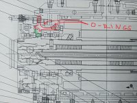
ok. I got it. Here is the correct parts manual page. No pins. U just have to adjust outer part of the coupling
Yes. The procedure looks tricky. I guess you have to estimate the amount you have to adjust, move it, assemble it and check milling tool clamp position. If you still out than you open it again and repeat every step again.
See, these procedures were not made to be given to customers, there are always little trick here and now Mazak personal uses. You, like running this machine in DEBUGGING mode with all interlocks ignored, or some other special parameter enabled.
ok. I got it. Here is the correct parts manual page. No pins. U just have to adjust outer part of the coupling
Attachments

Last edited:

")
