What's new
What's new

20hp RPC to power 10hp planer HELP

dmartin.dlm

Plastic
Joined
Dec 6, 2022
Hey everyone.
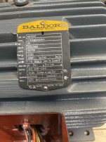
I’m building a 20hp RPC. My idler motor is a relatively new Baldor
20hp V:230/460 Amps: 50-25. RPM: 1760
3-phase motor. Service Factor: 1.15
NEMA Nom.EFF. 91% PF: 83%
This is most of the information on the motor and I’ll add a photos.
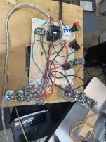
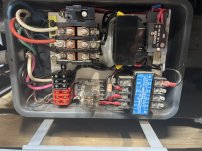
I have a a latching circuit for a 3-phase contactor and a momentary switch to 1,030MFD START capacitor to start the 20hp idler. And I’m using run capacitors between the incoming 240v and the Ghost leg.

Here’s the problem… I’ve got the idler motor up and running and I’ve got the legs pretty well balanced and these are my numbers
L1 to L2= 243Volts.
L1 to Ghost leg(L3)=264Volts
L2 to Ghost leg(L3)=263Volts
And Amps 5.5 on both L1 &L2
***but I’m new to this stuff and I’m not sure if I’m reading it correctly… I have an Clamp meter using the setting 400/600 AC A or
40 AC A.
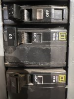
Also the power is coming from a 50amp break and I believe I have a 200amp panel.
The wire I’m using 10gauge 600v rated wire.
**** I was thinking 1 of the issues might be that I’m using 370VAC Run capacitors instead of the 400-plus ones. (I couldn’t remember the exact Volt those higher ones were)
All the wire to and from the contactor and the machine I want to power is 10gauge 600Volt wire except for the wire to from capacitor to capacitor and the latching and start switch.

I can the Machine I want to power is a 10hp 25” wood planer 3-phase 220/440v 60hz motor.
The RPC will start the planer but pop the 50amp breaker before it gets up to speed.
So I’m wondering if y’all can help me figure out what or where I may have gone wrong ?
And if there’s any ideas of how I can fix it.
Also I’m not sure what some of the idler motor information means. Like: the service factor, the EFF. , which I’m assuming is efficiency, and P.F. 83% and what/if they play a role in what the RPC can power up.
Oh and my RPC is currently laid out on a piece of plywood and MDF but I will be putting it in an electrical box when it’s done and working properly.
Thanks for any advice and suggestions!!!!
 

Attachments

  • image.jpg
    image.jpg
    2.1 MB · Views: 19
  • image.jpg
    image.jpg
    2.3 MB · Views: 19
  • image.jpg
    image.jpg
    1.4 MB · Views: 17
  • image.jpg
    image.jpg
    1.7 MB · Views: 14
  • image.jpg
    image.jpg
    1.3 MB · Views: 15
  • image.jpg
    image.jpg
    2.6 MB · Views: 18
10 gauge wire is only rated for 30 amps. Looked at my rpc, think I used 2 gauge wire but cannot see anything printed on the wires, measuring OD of the insulation its .310".

Edit: Looking at amp chart, I probably used 1 or 1/0 wire, I forget....
 
Last edited:
Ok thanks y’all. I’ll get a bigger breaker first and I’ll look a getting bigger wire.
Does anyone think the capacitors could be part of the problem?
 
Well ...
If you're blowing a 50a breaker in a few seconds you are probably drawing a lot more than 50a. 10ga is a definitely too small for 50a. 6 ga would be smallest for 50a breaker. How much bigger you need is uncertain, 60a would be the next step up but you likely need more. I'd suggest trying 100a with suitable wire. You also appear to have the ground and neutral tied together from your circuit breaker panel to your mdf board, which is not a good idea. 40a on baldor is likely power factor issue, not uncommon when a motor (or idler) is turning with no load.
 
Last edited:
Ok thanks y’all. I’ll get a bigger breaker first and I’ll look a getting bigger wire.
No, you need to add larger wires at the same time as the bigger breaker.

If you just add a larger breaker without the matching wires please let us know in advance, you might be eligible for a darwin award and a "finders fee" for submitting the story would be nice $$ to have ;)
 
Thanks for the correction. I took the neutral off.
What do you mean here
“40a on baldor is likely power factor issue, not uncommon when a motor (or idler) is turning with no load”
 
Ok. I didn’t realize that would be that big of a factor. I’m just trying to see if I could get it working. I didn’t think it would make that big a difference. I’ll move stuff around to get it closer to the panel and get some bigger wire.
And just so I’m clear for this project and any after this, You don’t think I can test with this wire ? Will the gauge difference between 10 and 6 make that big of a difference?
I hope that doesn’t sound snarky, I’m really just trying to understand? Thanks y’all.
 
If you're going all the way down the rabbit hole on this one, that motor is rated at 50A full load at 220V. Using that as a baseline for what your RPC could generate, for a two wire (single phase) load you multiply that by 1.73, which gives you 86 amps. Then you add some additional amperage for the current used by the generated leg capacitors. Then you multiply by 1.25 per @dalmatiangirl61's code reference. So a 125 amp circuit with appropriate wire. Much bigger than 6 ga, which is what you should have with a 50a breaker.

Quoting me earlier: "40a on baldor is likely power factor issue"
I misread your orginal post, you mentioned 5.5 amps idling, I saw the 40a meter setting. Please disregard that.

As far as "testing" with 10 ga, my 20HP RPC draws 209 amps peak on startup (tested with a Fluke clamping ammeter with peak hold). 10 ga wire runs about 1 ohm per 1000 ft. So if your cable is 20 feet long, that's a 40 ft loop. P = I*V = I*I*R, about 1600 watts lost to heat during that startup peak, about as much as a typical home electric space heater, if I did my math right. I'd say that's not smart.
 
Last edited:
Ok. I didn’t realize that would be that big of a factor. I’m just trying to see if I could get it working. I didn’t think it would make that big a difference. I’ll move stuff around to get it closer to the panel and get some bigger wire.
And just so I’m clear for this project and any after this, You don’t think I can test with this wire ? Will the gauge difference between 10 and 6 make that big of a difference?
I hope that doesn’t sound snarky, I’m really just trying to understand? Thanks y’all.
If you want to test it get a 100A or 125A breaker and the right gauge wire. That wire will be as big as your little finger but not quite a fat cuban cigar. Read the code sizing for wires posted above. I couldn't get into the link but it should be NEC code, not a local building code.
The small wire you keep wanting to use can melt since the breaker you are using is way to big for that AWG (wire size)
edit:
Here is a link to wire sizes by amps for different types of insulation:
Attachment is first page of the site, up to 400 amps. Looks like you need 1/0 or 2/0 , said as one-ought or two - ought cable
 

Attachments

  • Wire Size Chart.pdf
    507.8 KB · Views: 3
Last edited:
Firstly, agree that the breaker is literally there to stop wires from melting and you already have too small wire for the breaker. Definitely need bigger cable.

Secondly, 5.5A seems very low for a 50A motor, even at idle - only 11% of FLA. Are you sure it's correctly wired for 230V operation, not 460V? Can you post the inside of the motor terminal box?

I suspect the idler could be wired for 460V, given low idle load and a nice easy spinup, but very little ability to actually supply current as an RPC. It's acting more like a 5HP motor. Could be totally wrong, though.
 
Yeah the amp meter reading 5.5 threw me a bit. I am using a long cable wire probably 15ft. So that’s gonna go. I’m at the store now to pick up better wire and a breaker.
And what was weird was I had it connected to 12/2 wire for residential initially to test unloaded and I could swear it read 8.something originally.
I’m comfortable working with electrical stuff but realize I’m out of my depth on this.
Also I’m almost sure it’s connected low voltage but the cover over the wires might not be original but it seems pretty standard.
9-wire motor, all the wires are numbered and in color. 3-sets if 2 and 1-set of 3 which I believe is WYE ? Could that have something to do with it?
Also will the 10/3awg wire work for From the phase converter to the load ?
Thanks everyone and I’ll take a picture of the wire diagram when I get home.
 
Also will the 10/3awg wire work for From the phase converter to the load ?
Depends on how many amps your load can pull. This link seems to think you will be OK with 10AWG for 10HP motor, they say to use a 60A breaker though.
Shouldn't you have 10/4 wire so you also have a ground....
Link has links in it to follow:
 
Last edited:
Oh and my RPC is currently laid out on a piece of plywood and MDF but I will be putting it in an electrical box when it’s done and working properly.
I used plywood during RPC design phases.

From the breaker to the RPC board I would use #6 wire.
Then use #6 or #8 to the idler. Use #8 or #10 to the planer.

What would happen if you cycle starts to the planer. Spin it up right before the delta T seconds before it pops.
Then wait a second or two and power it again. Never did this myself.

Your 50A breaker in that size, may be the largest size amps. Hope not.
 
Last edited:
L1 to L2= 243Volts.
L1 to Ghost leg(L3)=264Volts
L2 to Ghost leg(L3)=263Volts
These line-to-line numbers will change when the target motor is turning. Those are the numbers used for balancing.
You may be out of tune and not even know it.

What are the values of the run capacitors?

Have you tried letting the idler run by itself for 5 - 10 minutes?

I have a welding machine that can take 110A input for full output.
When I fed it with a 50A breaker it would pop on just a power on with the machine front switch.
With a 60A breaker the pops went away.
 
Last edited:
My run caps are 370Vac and 275 total on L1 to Ghost (L3)
And 260 on L2 to Ghost(L3)
That’s the amount of capacitance I have on those legs. I haven’t put any capacitance between those yet bc I thought you had to wait until you put a load on it first to measure the amps ? But could I put 12.5mfd between L1 and L2 ?


Back
Top