What's new
What's new

3 phase starter circuit

The idler should not generate any current on any leg when being rotated by the pony motor. L3 will begain generating after single phase power to L1 and L2 create magnetic fields in the motor. This happens after power to the pony motor shuts down.

Here is a link to the ICM450 installation guide: https://cdn-assets.unilogcorp.com/ASSETS-H/DOCUMENTS/ITEMS/EN/UNI-03290_Instal.pdf

Look at figure 3 and what is written to the left.

Do you currently have the ICM450?

Get pencil and paper and draw out how you are intending to wire this up.
I cannot tell from what you are saying.
With lethal current and voltage involved there is no room for a "I thought you meant".

What can go wrong is : you die...
 
I don't currently have that item. OK I was thinking this thing starts in the NC mode and then stays that way only until a fault occurs. Now I see it starts one way when running properly changes state and then when fault occurs goes back to starting state.
1st)Open 2nd) when energized all 3 legs closes 3rd) if fault occurs back to open.
Can't operate contactor that send energy to idler like that. If there was only something out there that started closed and only opened upon fault that would be great.
Now OTOH I see that this would require a second contactor that will just cut off power to 3 phase panel in event phase loss imbalance, etc because of how the relay operates. The coil on that contactor can be operated via the ICM 450 relay. Not based on time, but rather based on everything running like it should be.
 
I called and talked with ICM technical support. The ICM450 can be powered by L1 and L2 with no power to L3. It will show a fault on start up unless it has a programed delay. The delay is programmed in seconds and can be up to 10 minutes long.

All times below are for example only. Wiring in an alarm for a ICM450 fault is not shown- but should be done.

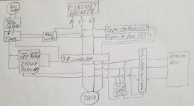
Figure 1 shows a single contactor/timer system. The ICM450 is powered by the magnetic starter. When start is pushed power goes to timer #1 and the ICM450. Timer #1 powers the pony motor for X seconds, then turns off and sends power to the relay on contactor #1 going through a relay on the ICM450. The ICM450 relay closed on its powering up. Powering up of ICM450 started a time delay of X+3 seconds. Contactor #1 closes at X seconds. If L3 is not generating and all voltages within parameters at X+3 seconds ICM450 opens its relay, opening contactor #1 and shutting down the idler.

Figure 2 shows a two contactor two timer system. When “start” is pushed power goes to timer #1 and powers the ICM450. Timer #1 powers the pony motor for X seconds, then switches power to the relay of the ICM450. This relay has one line going to contactor #1, and a second line going to timer #2. When timer #1 powers the ICM450 relay contactor #1 closes, the idler is powered, and L3 is generated. At the same time, timer #2 is powered and after a 4 second delay powers contactor #2, and the RPC connects to the breaker box. The ICM450 has its fault time delay set at X+3 seconds. This gives 3 seconds for the idler to generate on L3 and for the voltages to stabilize before it monitors voltage parameters and phase loss. If ICM450 sees a fault it opens its relay, cutting power to Contactor #1 and timer #2.

The single contactor/timer system of figure 1 allows L1 and L2 to provide utility power to the breaker box before current is generated in L3. This would be a short time, but it occurs, and could be up to 3 seconds due to the time delay set in the ICM450.

The two contactor two timer system shown in figure 2 is the better design because the second timer allows the RPC to be generating L3 to its full voltage before connecting to the breaker box. There will be no circumstance where singe phase power is transmitted to the breaker box.
 

Attachments

  • 20211206_120719 (2).jpg
    20211206_120719 (2).jpg
    83.8 KB · Views: 17
  • 20211206_120736 (2).jpg
    20211206_120736 (2).jpg
    83.6 KB · Views: 24
I called and talked with ICM technical support. The ICM450 can be powered by L1 and L2 with no power to L3. It will show a fault on start up unless it has a programed delay. The delay is programmed in seconds and can be up to 10 minutes long.


Figure 2 shows a two contactor two timer system. When “start” is pushed power goes to timer #1 and powers the ICM450. Timer #1 powers the pony motor for X seconds, then switches power to the relay of the ICM450. This relay has one line going to contactor #1, and a second line going to timer #2. When timer #1 powers the ICM450 relay contactor #1 closes, the idler is powered, and L3 is generated. At the same time, timer #2 is powered and after a 4 second delay powers contactor #2, and the RPC connects to the breaker box. The ICM450 has its fault time delay set at X+3 seconds. This gives 3 seconds for the idler to generate on L3 and for the voltages to stabilize before it monitors voltage parameters and phase loss. If ICM450 sees a fault it opens its relay, cutting power to Contactor #1 and timer #2.


The two contactor two timer system shown in figure 2 is the better design because the second timer allows the RPC to be generating L3 to its full voltage before connecting to the breaker box. There will be no circumstance where singe phase power is transmitted to the breaker box.

what's the advantage of ICM450 relay closing 1st 200 amp contactor? Let that be done just by a timer relay I am thinking. I see it only as having a use for opening a 2nd contactor (no timer relay needed) if there is a fault in power coming out of RPC. NO need for fault time delay and it closes only after L1 L2 and L3 are in good balance, output, etc etc. I just mount a two light strobe in the shop. Green for on/running good and strobing yellow for fault identified by ICM when relay changes state. BTW thanks a lot I wouldn't be getting anything near this good worked out without your help.
 
Suppose you throw the belt or it breaks, the neighbors pet rat escapes and chews up the wiring. The local python smells the rat and wraps around the belt, and pulls the chewed wires clean off...

However it happens- the idler is not turning and you are pulling lock rotar amps. The ICM450 has prevented the breaker panel from getting any current- but the idler is still not turning and will be powered until the circuit breaker trips. This is what occurs with timer#1 wired directly to contactor #1.

With EVERY start of the RPC there will be a short time that the only current will be in L1 and L2 as L3 is not generated yet.

The ICM450 has to have a time delay to allow for this to end and the generated leg voltage to stabilize before it starts its protection. If not- it will shut you down on every start.

With the single contactor/timer version (figure 1) this short single phase and voltage imbalance goes to the breaker panel and to whatever is wired to it with every start up.

The two contactor two timer version (figure 2) uses timer #2 and contactor #2 to prevent this

There are MANY ways this could be done.

As I said before- YOU need to be the one doing the drawings and deciding what you want.
 
throwing around ideas here. Keep in mind I plan on keeping thsi thing on top of concrete and a small sealed bldg around it made out of vented vinyl soffit with plenty of 4X4( encased in vinyl fencing wrap) support. doubt the rat, snake pet dinsoaur scenario will happen. This thing will be as reliable as the Larson RPC.
 
Was at work started to draw my idea ( forgot all the drawings at work)and I drew what I was thinking. Then it hit me, U R A Genius. ICM450 cuts off power to idler if anything goes wrong. Anything under the sun almost. Murphy has some say in this matter, but using the ICM like that weakens his powers by a lot. Now I am thinking I don't see how to improve on that. Just use SUPCO "break on make" timer so we can give that second relay a delay and get going. Going to pass these drawings by some aforementioned friends.
 
I purchased an ICM450 off e-bay, and have been trying it out. I misunderstood its behavior as it powers up. The two designs in post 43 will not function as intended Will post modified design after testing its functions further.
 
Here is the revised diagram.

To start the RPC the magnetic switch is used. This provides 240 volt current to #1 timer, which runs the pony motor for 8 seconds, then cuts off the current to the pony motor, and routs it to the coil of the 3 pole contactor connecting the idler. This path has two parallel relays. The first one is a time delay OFF relay. The second is a Normally Open relay with a 240 volt coil. The current from the timer #1 flows through the time delay OFF relay for 2 seconds, and the relay opens. During that 2 second time the contactor to the idler opens, power is generated in L3, and the run capacitors are connected. As power is generated in the manufactured leg, the NO relay between timer #1 and the 3 P contactor closes. This routes power to the contactor coil after the time delay OFF relay opens. As the idler is powered on , so is the ICM 450. The ICM450 takes several seconds to power on, and by the time it does, the generated phase is present, no phase loss is detected and the ICM450 relay closes. This closes the second 3 p contactor and current goes to the breaker box.

If the pony motor fails to spin the idler, the idler will only be powered for 2 seconds.
In my opinion the ICM450 is not well suited to cutting power to the idler. It could be done, but I see no advantage in this.
 

Attachments

  • 20211213_195415.jpg
    20211213_195415.jpg
    84.9 KB · Views: 12
Any bit more complex and its time to bring in a PLC? Thanks for the idea. What went wrong when you tried to use the monitor to kill the idler? Did it not want to close the relay during the interrogation period or something else. My monitor hasn't arrived yet and I am afraid won't be able to test it on single phase. Maybe and I doubt this, the neighbor will let me try it out on his 3 phase?
 
The time between powering the ICM 450 and its closing its relay is about 9 seconds. It appears to me it starts functioning about 1.5 seconds before that.

I wired it to my capacitor start RPC with some indicator lights so I could tell when the idler was energized, and when T3 connected to the ICM450, which was through an adjustable delay ON timer. The timer I had for this goes up to 180 seconds and is not digital, so no way to select a specific time. Timer is not ideal for this- but is what I had.

With the timer and a number of trials I was able to determine a setting where it could work. The challenge is that for a pony motor RPC you would need to use several timers. One for the pony motor start. One to bypass the ICM 450 so you can power the idler before before the ICM starts monitoring then turn off right after then, and another timer to start the ICM 450 so it starts its monitoring at just the right time.

A phase not being present is considered a critical fault, and you cannot delay its being monitored on startup beyond what it currently is.

It is not impossible to use a ICM450 to monitor for the idler not turning on startup, but it is much more complicated than I initially thought it would be.

Using T3 to power the coil of a relay is much simpler. You could have T3 go to the coil of the idler contactor- but you would need to have it go through a NO relay powered through the magnetic starter so you can turn the system off. This is different than what I drew out - but no simpler. See post 27 in this discussion. Need wiring advice from RPC to 3-phase sub-panel. Problems with single phasing?

I thought about using a potential relay- but they are NC and open when a voltage level is reached. To use one requires a more complicated design to do the same thing.
 
With the timer and a number of trials I was able to determine a setting where it could work. The challenge is that for a pony motor RPC you would need to use several timers. One for the pony motor start. One to bypass the ICM 450 so you can power the idler before before the ICM starts monitoring then turn off right after then, and another timer to start the ICM 450 so it starts its monitoring at just the right time.

sounds like too many timer relays that way. so might as well go with original idea that ICM just cuts off last/output contactor.
 
Use this for the 240 volt relay to the idler contactor and you can adjust the voltage it closes at. MACROMATIC Voltage Sensing Relay, 240V AC, 10A '@' 240V, 8 Pins, Mounting':' Plug In, SPDT - 45LV09'|'VAKP240A - Grainger
https://www.grainger.com/ec/pdf/45LV06_1.pdf

Strostkovy reports the coil of a 240 V contactor drops out when the generated leg drops to 160 -170 volts. I do nogt know if that would be true for a typical 240 volt relay.

The ICM450 would work on the last contactor unless the voltage drop on starting a machine is too great. Per my understanding of its operations guide, it considers phase loss to be a voltage drop of 25% from nominal on any phase. If nominal voltage is 240, 180 volts would be phase loss. This is a "critical" fault will always open the devices relay, and with no delay. While that 25% is not adjustable, YOU set the nominal voltage. If you are having high loads and voltage loss shut you down decreasing the nominal voltage might help.

Non critical faults are unbalance, high, or low voltage, and these can have a fault interrogation delay of 0-15 seconds and Delay on break timer of 0 to 10 minutes. Both under and over voltage are adjustable from 2-25%. Voltage imbalance 2-20% adjustment range.
 
The idler should not generate any current on any leg when being rotated by the pony motor.................................................

But it may.

All that is needed is the right value of capacitor, and a small residual magnetic field in the iron, and the "motor" can become a "generator". If unloaded, it can "build-up" voltage. Now, whether the balance capacitors are sufficient to do that, is a question. It could be close, since the conditions for good balance and good build-up are not that far apart, both are near resonance.

The result of such a thing happening is that the motor will become bogged down, and the voltage on the capacitors will go sky high. A good deal of current will circulate through the capacitor, and a fair bit of load is put on the driving motor.
 
JST Yes, A caution about that is why I initially responded in post #7

My solution was to have the one pole of the 3 pole contactor to the idler connect run caps See figure in post #50.

It just now occurs to me that what I have drawn out puts run capacitors between L1 and L2 even when the RPC is off. (My initial thought had been one bank, not two.) Would the above design increase the voltage between the L1 and L2- but with those being fed from the single phase service, that would imply an increase in voltage from the transformer on down.... I have read about capacitors between L1 and L2 for power factor correction. Would the two banks wired this way act as power factor correction capacitors for that service prior to the RPC being started? Should the design be modified to use a separate contactor to connect the run caps?
 
Strostkovy reports the coil of a 240 V contactor drops out when the generated leg drops to 160 -170 volts. I do not know if that would be true for a typical 240 volt relay.

If that happens it's time to drop out. Trying to run a CNC on this. Instructions say 10% balance I am aiming for better than that. 187.2-229 VAC.
 
JST Yes, A caution about that is why I initially responded in post #7

My solution was to have the one pole of the 3 pole contactor to the idler connect run caps See figure in post #50.

It just now occurs to me that what I have drawn out puts run capacitors between L1 and L2 even when the RPC is off. (My initial thought had been one bank, not two.) Would the above design increase the voltage between the L1 and L2- but with those being fed from the single phase service, that would imply an increase in voltage from the transformer on down.... I have read about capacitors between L1 and L2 for power factor correction. Would the two banks wired this way act as power factor correction capacitors for that service prior to the RPC being started? Should the design be modified to use a separate contactor to connect the run caps?
Looks like we need to add another 2 pole contactor for the caps and engage that after idler rotating on own power. What amperage we talking here? I had a funny feeling in beginning about those caps. THanks guys, this is what WE were talking about having a look over before implementing things. Good catch JST. Thanks.
 
Madmachinest---- To drop the voltage to the 160-170 range would mean you were starting a load too large for your system and have a severe overload.


JST some more questions. in a different thread--- (https://www.practicalmachinist.com/...former-phase-converter-375393/index4.html)--- ----you stated:

"I would suggest an autoformer that boosts the generated leg to be perhaps 5% to 10% high at no load, which will probably still be reasonable compared to the pass-thru voltage with a heavy load.

That, so long as the autoformer does not add too much impedance (don't skimp on the VA), would seem to be the best approach. Alternately, feeding the entire idler a boosted voltage separately from the pass-through is reasonably equivalent, but may be less flexible as to the voltage.

The actual best approach may be an idler that is wound with a few more turns on the generated leg, to bring it up to the slightly high unloaded voltage. That is the least complicated, potentially the least added impedance, but requires either a re-wind, or a custom product. And it may be limited by available wire space in the stator iron.

Since the idler is known to be low output as far as voltage, inherently, all the various techniques come down to different ways to get a good generated leg approximation to the correct voltage/phase at a chosen load point. The phase should be inherently pretty good, but "balance capacitors " can drag it off a bit.

The capacitor methods all suffer from sensitivity to the load. The usual way to deal with that is to set the thing up for a near-full-load situation, where you need it most. That tends to risk a wildly high voltage at low or no-load conditions, which can force a less-than-ideal compromise The phase may also shift, and the best voltage may not have as good phase or load current.

The goodness of a transformer approach (or motor turns approach) is that it only introduces voltage boost, with minimal other effects."


Later in that discussion SAF provided a link--- Dropbox - Richardson Induction Phase Converter.pdf - Simplify your life ---to a PDF of the Richardson paper.


My questions are:

Would an autotransformer and capacitor system be a better solution?

It appears the autotransformer supplements the voltage generated in TE, so the autotransformer does not have to be sized to provide all the current on the generated leg. Is this correct?

Would it be possible to use a PLC to drive a servo controlled Variac to provide a stable voltage in T3 as loads vary?
 
An autotransformer on the generated leg ought to be able to handle at least whatever current flows in the generated leg. If a bit larger, that will reduce series impedance. You do not want too large, or it may reduce the available current just by what it draws w/o load.

I don't know what advantage a capacitor WITH the autotransformer would have. The whole idea of the transformer is to avoid using resonating (balance) capacitors, since they are not stable under load.

A PLC setup could work, although it would not do well with faster transients, like a motor starting. Mechanical action would not be as fast as the electrical effects. Not at a reasonable cost, anyhow.


Back
Top