What's new
What's new

3C headstock identification

jkopel

Stainless
Joined
Apr 3, 2010
Location
Seattle, Wa USA
Not sure if this belongs here or in the antique section but I purchased this small lathe and am looking for help identifying it.
I guess it does not matter that much who made it, but I would like to try and disassemble it for cleaning and a name might help turn up some drawings.
There was once a name plate riveted to the end of the bed but I am not even convinced the bed and headstock started out life as the same machine.

Maybe the shape is familiar to someone?
It has the Hardinge style taper lock nose, but it is for those tiny 3C collets.

Any hints would be appreciated!
Thanks,
Josh

(I used to know how to do this, not sure why the pics are so small)
IMG_9016.jpg
 
96d40f00693885fc3119f7e9ca402db2.jpg

0ebd7e28de9edbd89aaca48cb15f0761.jpg

adeb6a93aa811af7e2c06c7fff335a1d.jpg

94e99891c3e1acad0696a061031e97e6.jpg

d396079f9d22c282a71e746b97af12ea.jpg
 
Probably hardinge. Look on the front of the casting under the spindle for a s/n. Elgins had a slightly different pattern,shown below. Note the s/n location.

BB59_8.jpg


BB59_7.jpg
 
Thank you Jim, I’ll clean the gunk off and see what I find.

I am thinking it is a tapered plain bearing in there and I have to remove the front and back retaining plates and unscrew it from the back somehow. Does that sound like a reasonable guess?
 
Thank you Jim, I’ll clean the gunk off and see what I find.

I am thinking it is a tapered plain bearing in there and I have to remove the front and back retaining plates and unscrew it from the back somehow. Does that sound like a reasonable guess?

I have some similar Hardinge No. 3 headstocks, and some No. 4 and No. 5. That is a ball bearing head, and they were made from around 1938 to around 1955. Note that Hardinge used three screws to retain the bearings and Elgin used four, plus the pattern differences. There will be a pair of precision angular contact ball bearings at the right end and one radial ball bearing at the left end.

I have a couple of short Hardinge beds about that length, but they are different from each other and different from the OP.

The Hardinge name, size (37) and serial number should be stamped on the machined right-hand end of the headstock just under the bearing retainer. Here is one of mine, with the stamping almost visible.

BB37 2.JPG

Larry
 
Thanks Larry!
You and Jim were correct, I was able to uncover the serial number. 37-22396 if that means anything…
I appreciate your letting me know it’s a ball bearing headstock. I will probably not try to disassemble it since I’d most likely ruin it in the process.
73733de66781af1855f0066e29849797.jpg
 
The 37 means it takes 3C collets and has a 7" swing. No. 22396 was built in 1944.

The more common bed for that headstock would be long enough for a conventional tailstock or a turret. I have never owned that style bed, but here is a picture of it, along with the correct tailstock, from an old eBay ad with too much shipping cost to make me buy it. And here are two pages from a 1946 catalog.

Some of these ball bearing headstocks were bought as replacements for older plain bearing heads and ended up on earlier round beds. Hardinge kept the same bed top dimensions from 1903 to around 1955, so it is common for older and newer design components to be found on one lathe.

The 1940's open headstock bed was styled just like the bed for the TR and ESM enclosed headstock/underneath drive beds. I call it the skirted split bed.


Skirted bed for open headstock Dimensions.jpg Skirted bed lathe 1.JPG Skirted bed lathe 2.JPG

Larry
 
Thanks that’s interesting about the bed length. I assumed it was some sort of “speed” lathe or chucking lathe. This is only 18” long!

There is about .0005” runout on the external taper and a bit more wear in the collet taper. It also has another thou of end play pushing/pulling on the spindle. If I want to try and adjust the end play do I need to figure out how to slightly tighten the ring with 4 holes at the back? It turns very freely (after pulling out the incredibly encrusted draw tube), but it also makes some minor crunchy sounds when spinning. I guess I might need to pull it apart after all.
acb7003875b74cea9130ced8c7c2ca9e.jpg

7451bce480926e0adb90b4499a2145f3.jpg

7477bfab0bea57d23b582d6276f3dcf6.jpg
 
There is no endplay adjustment provision. Make sure the nut on the left end of the spindle is very tight. The pair of angular contact bearings are designed with some degree of preload when both inner and outer races are tightly clamped together. If the nut is tight and there is endplay, the bearings are worn. Or maybe someone assembled it carelessly. The radial bearing outer race floats lengthwise in the casting and has no influence on endplay.

If there is no lube fitting on the left bearing, it would have been greased "for life," probably expected to be less than 77 years of constant use. Your lathe might have only been in use a short time, of course. The oil cup at the right end indicates the pair of bearings were to regularly get spindle oil.

I made wrenches for working on some of my Hardinge heads. Start with a steel tube and insert two steel dowels in one end to catch the holes in the spindle nut. Use a spanner to turn the tube. Your model may have enough access to the nut to use an adjustable face spanner. I hate to see ugly punch marks on these nuts.

DSC00347.jpg DSC01954 (2).jpg DSC01955 (3).jpg

Your bed has an interesting serial number mark. I say that because I found another picture of that BB37 head from my post #5 that clearly shows the Hardinge serial number and a second serial number, not from Hardinge. My head's second number is 14293 and your bed is number 14230. I think the two numbers were stamped with the same punches. My head was built with tight and loose pulleys on the spindle instead of a step pulley, a design ideal for single speed, repetitive jobs with quick starts and stops. I got it decades ago in Chicago with no bed. Chicago had many small shops with old Hardinge machines and shops that used Hardinge parts to build special equipment. Then there is the Elgin Tool Works Division of Hardinge Mfg. Co. in Chicago that made Hardinge Brothers-like lathe stuff during WWII. The war created a huge demand for machine tools and clever people did their best to help out.

Hardinge BB s-n 37-23644.JPG

Larry
 
Those tools look exactly like what I need to make, thank you!
I am somehow not surprised by the serial number stamp coincidence, the internet makes finding these odd connections easier but I am sure they exist all the time.
Your (and other folks) willingness to help and share your knowledge is always appreciated, I think after reading a few other posts I may take it apart after all and see what I can do about flushing the front bearings and re-greasing the rear.

I am hoping to make a custom machine for deep drilling smallish (.0625") holes in .125" rod for hinge knuckles (it's a long story). I may not be quite as clever as the people doing that war effort, but with any luck this old headstock will keep turning.
 
Unfortunately if the spindle shows *any* axial run-out (given the clamping nut on the backside is tight) that means the bearings have worn to th point where the preload (which in the case of the elgin shown) is built into the front bearing pair, has gone from positive preload to negative preload - that is, clearance. Mine had about one or two thousanths of axial play when I got it also. The bearings looked OK on disassembly but had worn to matte finish on the balls and races.

I replaced all three (radial bearing at the left end and angular contact pair at the front) which cost a bit. Larry can probably tell you the bearing configuration before you open it. More photos of the elgin:

BB59_1.jpg


BB59_4.jpg


BB59_5.jpg


BB59_6.jpg


BB59_2-6.jpg


A word about lubrication: apparently lathe manufaturers of that era could not make up their minds about the best way to go about this. Oil, grease, grease fitting? This elgin I believe originally had oil cups and that's what I put on it, replacing grease fittings probably from a previous owner. The wheel bearing grease probably was an attempt to keep the machine running after the bearings were badly worn.

The paper gaskets shown in one photo seal the oil and are actually sized in thickness to develop the correct preload on the front pair. The rear bearing is pure radial and has the outer race float axially in the casting bore - i think in one shot you can see the marks where the race sits inside the bore. The iron casting and the steel spindle have different thermal expansion numbers so there has to be float somewhere in the system.
 
I got the bearingd from Alpine Bearing. They were hepful in matching what I needed from the originals. It's probably worth doing at least the front pair as the expense is not *that* great. You are lucky this spindle has the externally-acessible collet key. Mine was buried under the front bearings ao that was a must-change while I had it apart.
 
thanks Jim, I guess I will first make sure the back ring is tight but I have to pull the collet closer "spline thing" first and try a pin spanner or make a tool like the one Larry showed.
Not sure if I will go all the way to getting new bearings but I will see what they cost these days.
I think you replaced yours some time ago, correct?
In any case thanks for taking the time to post those pictures they are very helpful.
 
Tried tightening the rear ring but it made no difference in the axial play, so apart it comes.
Might be useful to someone someday so here are my disassembly photos.
1. Finally found a use for this old air force pin spanner with multiple tips to get the ring off.
c2cbace98c1e37f4f41627cb3d725fa7.jpg

3f1937f39f2122c936d6fb0570291dda.jpg


2. Removed the bearing cover (not sure what to call it). I could not figure out how to get a puller on it so I gently tapped on the angled notch with a brass punch to rotate it until the gasket broke free.
b87c7b78048d3ff5315322d37b6f5c78.jpg


3. there is another threaded ring in front of that cover and behind the rear bearing. it needed a different weird pin spanner which i luckily had. I had to put the bolts back in and a pin punch through the pulley stop hole.

23e86f5454ac8e3a0cf6589a8d781753.jpg


ce40a7ce9b11a71d5b7f3320a8e377b6.jpg
 
4. with those out i could easily remove the rear bearing (bone dry) and the inner bearing cover.
277deb2f35f08b495fa417a71ab836e3.jpg

f2cbdfd01d35e776913ddac0f27d0712.jpg


5. at this point I could just pull the whole spindle out the front. To my surprise the pulley is made in two pieces.
13abfec9c5ab073c6f5280dcf5d2b62f.jpg


7. The pulley comes off easily, but there is a long thin key that I had to very carefully tap out with a small center punch in the very end. I was sure I would destroy it but it finally came free with just a little burr that will file off. (no picture, too busy swearing)

8. I had to push off the bearings and front cover plate in the press until they cleared the shoulder they sit on.

d7378dd37ed692d7d852ef3641598f6c.jpg


That’s it. Much easier then I feared.
To my uneducated eye the bearings look ok, but the brass cage probably means they are ancient. I thought there would be a preload washer in between the pair, but no there wasn’t.

K3 7210 B(and a handwritten)G

6290e46f24d0cd4f273cdeffb7fbb1c5.jpg
 
I will point out that the 3C, 4C and 5C spindles for this model headstock have identical exterior dimensions, so they can be swapped for a different size. The bodies came in 7" and 9" swing, so they can also be swapped. For some reason, the threaded nose option was more common on the 4C size.

Larry

BB open headstock spindle ends (2).JPG BB open headstock spindles (2).JPG
 
The front is an angular contact 7210 pair. The preload is built into the pair, and devlops when both the inner and outer races are clamped in contact. Inners via the nut and spacer stack on the spindle (hence the 'two part' cone pulley, the inner part is really a part of the preload stack, precision ground end flats) and the outers via the two side plates. Again note that the gaskets need to be a particular thickness when clamped up. I'll try to see what my original bearings were. The bearing balls in your set will probably look "OK more or less' but will have a very matte finish on them.
 
Also look to see if there are match marks on the ODs of the outer races. See the 2, and 3 on the replacement bearings I had shown above.
 
jkopel,

That's a nice disassembly description for these ball bearing headstocks. Thanks! I wish I had seen one like yours to look at when I took my headstock apart years ago!

The reason you didn't see any difference when you tightened the rear ring is probably because that ring was tightened against the ring ahead of it and they couldn't move together to take out any slop in the front bearings. When they are not tightened together, the forward ring is tightened as much as possible to push the two front bearing inner races together metal-to-metal, and partially set the bearing preload. Then the aft ring is tightened against the forward ring to keep the two in position. When the front bearing retainer is clamped in position with the proper gasket thickness as noted by Jim, then the outer bearing races are clamped metal-to-metal, and the proper bearing preload is set. The gasket thickness has to be such that it allows the bearing races to be clamped metal-to-metal and not allow the retainer to bend.

I have a ball bearing headstock like yours, SN 59-16400, so it's slightly older but made the same. It came with the threaded nose spindle but I swapped a 5C tapered nose spindle into it. Mine had grease in both sets of bearings, although it had an oil fitting like yours in the front. But considering it's age, who knows what had been done to it. The rear bearing was dry like yours, though. I cleaned up the bearings and put grease in both sets, and it runs just fine.

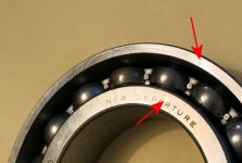
On a set of similar bearings I have the match marks look like little polished circles that you can see if you get the light just right. They are on the "open" side of the angular contact bearings, the side that has the thinnest outer ring thickness. Here's a picture showing them. They are pointed to by the arrows and are hard to see. Your bearings may or may not have the same type of match marks, and I may be telling you something you may already know.

attachment.php


Unless you already did this, it would have been nice to put match marks on the inner races of the bearings and on the spindle so you can put them together in the same orientation. The same goes for the outer races and the housing.

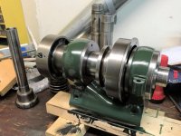
BTW, here's a picture of my headstock. The spindle I put into it came out of an enclosed headstock. Larry mentioned the 3C, 4C. and 5C spindles all fit into the same ball bearing headstock, and in addition it seems the "ball bearing" spindles of the enclosed and open headstocks all fit together. And I've had a little Hardinge BB4 mill apart, and it has the same spindle as the enclosed headstock, so all of the "ball bearing" spindles of the these open and enclosed lathe headstocks will fit into those mills. It's just when you get into the enclosed lathe headstocks that don't have the brake spring boss on the top and the drive belts in the middle that you lose the interchangeability. You can see the write up on headstocks on Tony's Cataract pages (Cataract Lathes) to see what I'm talking about as far as the enclosed headstocks are concerned.

attachment.php


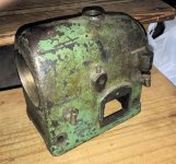
Here's a picture of the enclosed headstock from which I took the spindle in my headstock.

attachment.php


Irby
 

Attachments

  • IMG_5633_1.jpg
    IMG_5633_1.jpg
    51.3 KB · Views: 63
  • IMG_3283_1.jpg
    IMG_3283_1.jpg
    78.3 KB · Views: 63
  • IMG_5634_1.jpg
    IMG_5634_1.jpg
    95.5 KB · Views: 63
Nice paint on the green headstock.

For the record I went back and found the original stuff from when I did those headstocks. The "111" bearing listed from alpine, is an angular contact pair. The original bearings are listed with their part numbers shown, which Alpine crossed to the ones I purchased. I did not photo that, but the packages for the replacements had two numbers listed on each set, where the numbers were each 2 microns. I suspect this says something about the runout of the bearings when installed.

One of the photos shows a calculation I did to get the gasket thickness - the penmanship is a bit questionable but the numbers are a difference between the available space in the headstock, minus the thickness of the bearing pair, divided by two to get the desired gasket thickness.

The other photo showes details of the spindle configuration and what spacer goes where.

As an aside, if you do replace your bearings you basically have one shot at installing them, if you press the front pair back off for some reason, you'll be pressing through the balls and will degrade the bearings if this is done. I included the alpine packing slip just to show their information, your bearings will be different numbers, no doubt.
 

Attachments

  • elgin_original_config.jpg
    elgin_original_config.jpg
    39.1 KB · Views: 9
  • elgin_original_fronts.jpg
    elgin_original_fronts.jpg
    56.4 KB · Views: 9
  • elgin_original_rear.jpg
    elgin_original_rear.jpg
    89.9 KB · Views: 9
  • elgin_rear_config.jpg
    elgin_rear_config.jpg
    97.6 KB · Views: 8
  • elign_replacements_alpine.jpg
    elign_replacements_alpine.jpg
    90.2 KB · Views: 9


Back
Top