What's new
What's new

Abused Biax BL-40 teardown (and fixup?)

Bakafish

Hot Rolled
Joined
Feb 21, 2022
Location
Tokyo Japan
5 Biax BL40 Green Body scrapers appeared on the local auction site, one of which was clearly new-old stock, the other 4 were all pretty hammered, but all of them had $20 starting prices. The appearance of these rare beasts always starts an anxiety clock in me, even though I own a pristine one now, I live in fear of irreplaceable part failures and the appearance of these on the auction sites triggers my hoarder instincts. I was preparing myself for the inevitable last minute bidding wars that would go on, the catch was, the VP of my company (and old friend) had scheduled to visit Tokyo and I had to entertain him and some of his local staff exactly at the time the auction closed. I don't want to make everyone sad with how cheap the boxed one went for, I wasn't able to covertly throw a successful bid on it, but I did manage to take a bathroom break and get the last of the battered beasts for about $400, so I can't really complain.

obiax1.jpeg
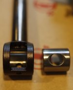
The blade is a home built unit, basically exactly the same Tungaloy hand scraper blade as the ones I modified, just an older version with a slightly different (possibly superior) clasp.

blades.jpeg

The unit it came with is on the left, and my two home made units are on the right.

The unit arrived this morning, the power cable was disintegrated to the point I wasn't going to try to power it up so, "Let's take it apart!"

There are lots of places where disassembly of these are documented, I'm not going to pretend this will be the canonical teardown, but I think every example helps as these still feel to be poorly documented as far as service is concerned. Hopefully I'll be able to add something to the information space. The disassembly steps and work will be in following posts, no promises on the timelines and it may be abandoned if there are some show stoppers.
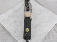
obiax2.jpeg

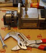
The condition seems poor, but serviceable. There are broken parts and some truly sad hacks (all 4 used units had the troublesome power switch cut away and exposed as seen above) but mechanically is still seems like I can get it running again.

parts.jpeg

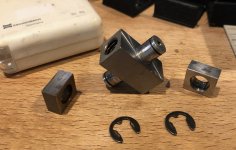
On first inspection I noticed a missing piece, one of the "Adjustment Plates" and the "Rubber Section" of the blade holding shoe is badly degraded and needs to be replaced. My experience with the US Biax distributor has been one where they refuse to respond to any form of contact. I suspect that this part is interchangeable with the newer Black Body BL40's, but would love to get confirmation of this as it must be hardened and ground and difficult for me to make at the moment.
 

Attachments

  • blades.jpeg
    blades.jpeg
    306.7 KB · Views: 8
This is not hit-and-run, just getting my ducks in a row. I haven't heard from Biax about the parts I need, what's the deal with Biax and its distributors? Anyway, the wear plate isn't a particularly complex part other than the fact that it is hardened. It gave me an excuse to pull out my hardness tester, although it was kind of an academic exercise as I knew it was hard and I don't think the exact value is super helpful.

hardness.jpeg
This is a Mitutoyo unit (labeled as a spin-off at the time) that has a pretty broad hardness testing range, it is in Rockwell C mode.

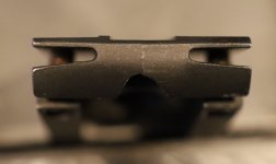
But although I ordered some 2mm thick hardened tool steel plate, I don't want to deal with lapping it and drilling the two 4mm holes that are required if I can avoid it. So I got some Phosphor Bronze plate as well and will try making a new pair out of that first. Closer inspection of the shoe shows that the machine was run with only a single wear plate for long enough to cause different amounts of wear on the two surfaces of the shoe. Since the shoe is mounted on a rod that constrained the wear around its axis, the wear on that side is at a slight radial angle. Ideally these surfaces would be reground even to each other and parallel to the wear plates, but as long as the clearances are correct and the plates are shimmed properly, I do not feel it will matter at all.

I stoned off a small sharp lip along the edge of the worn side of the shoe. The difference in the two surfaces is a few tenths of a mm, not great but easily shimmable. The bronze will wear faster, but I suspect given my limited usage and the ease of making new ones, this isn't a deal breaker. If it doesn't work then I'll deal with making holes in the hardened steel, or work harder to get factory replacements.

The other suspect parts are the rubber insert for the shoe and the power switch, which has a cracked case and the rubber gasket had totally degraded. My friend in the Netherlands was kind enough to get me a New-Old stock switch replacement off of Amazon.nl, and the rubber is something that I can cast, carve or print.

power.jpeg

I've been doing my best to take lots of pictures of what I'm doing, but documenting everything really gets in the way of my desire to get things done, so there's been a lot of 'Damn, I should have made a photo of that' followed by resentful disassembly to take a picture of work already completed. Having this second unit is great as far as giving me the assurance that the pristine one can be serviced and I know where everything goes and that I won't bork it.
 
So the disassembly of the Junker machine started with removing the blade retainer (spring shoe) [73], retained by a single cap head screw. This exposed access to the (2) flat head screws that affixed the scraper shoe [69] to the reciprocating shaft (scraper spindle) and once that is removed the (2) adjustment plates [70] will come off, each being held in position by two 4mm pins.

shoeless.jpeg

This allows the front housing to be removed after freeing the (3) nuts that hold it to the gearbox section, the top nut also fixing one side of the leather hand strap. With my machine the shaft stayed with the front section as the grease had become quite stiff, but there really isn't anything tricky about this operation. The shaft has a precision fitting pivot assembly that engages with the wobbler finger, mine was very stiff but there was no slop and minimal wear to the sleeve bearing surface itself.

thrust.jpeg

Removing this housing exposes the clever wobble drive that converts rotational movement into linear motion, and more importantly allows the adjustment of stroke length. On Junker, at this point I tried turning the adjustment screw, but it seemed quite stiff, so I deferred further investigation until later. Like the outsides, internally it was quite dirty and there was a lot of fine metallic contaminants, but the bearings seemed smooth and without play and there was no surface corrosion. I did see witness marks of prior disassembly on every screw and part though.

The next step of disassembly I undertook is only required if you want access to the wobble head shaft main bearing [39] and requires a 4mm pin punch inserted into the hole located in the bottom of the gearbox section that engages into a hole in the main shaft and locks it. The wobble head had a pair of flats that are ~45mm apart, but the larger Knipex adjustable parallel wrench handles it with no problem, and it unthreads from the shaft on standard threads (there are no reverse threads anywhere I could find.)

wobble_remove.jpeg

Removing this head exposes the bearing retainer ring that my Mitutoyo small hole transfer tools revealed utilizes a very non-standard 4.5mm pin-spanner hole size. This ring was extremely tight, and as the bearing felt good I decided not to risk damaging the nut with the wrong pin sizes in my adjustable pin wrench. I did buy an extra set of pins for my wrench that I can machine or grind down from 5mm to 4.5, in case I ever need to replace it.

trans.jpeg

To detach the gearbox section from the motor and expose the internal gear train there are (4) long phillips screws in the now exposed face of the gearbox section. However, you may first want to open the rear plastic housing held by a single T-20 Torx screw and remove the two carbon brushes, as pulling the motor out may cause the armature to pull out and damage them. There are 4 small brass sleeves around the screws that ensure proper alignment with the rear section of the split gearbox housing, and one sleeve to align that rear section with the front housing, so make sure you don't accidently drop them when taking these sections apart.

sleeves.jpeg

Junker's gearbox was full of evil looking grease, but fortunately there was no sign of the dust contamination the rest of the machine was suffering from. The small layshaft that transfers power from the motor to the main gear is retained by needle bearing assemblies on both sides, and is easy to remove. There is the main shaft that has an angular front bearing, retained by the aforementioned lock ring and a rear bearing that appears to be a deep groove type according to the parts listing. I probably should have pressed out the shaft to ensure that all the old grease that was between the two bearings was removed, but after cleaning it spun very freely and quietly, and it wasn't clear to me how to reset the preload if that front bearing was truly angular as indicated. The gearbox was carefully cleaned and an ample amount of new Lithium grease applied.

filth.jpeg
I removed the armature, and found that the front 608ZZ sealed ball bearing was a bit crunchy and noisy, so it was replaced. The rear 627ZZ bearing seemed good, and wasn't a size I keep around so I left it in place. The disassembly was not as intimidating as I had feared, so other than that tricky main shaft, replacing any noisy bearings isn't really a fear anymore.
 
At this point I circled back to the wobbler adjustment screw being stuck. I checked the effort to turn it on the pristine Biax, and it was basically very easy to turn, so I knew there was a problem with Junker. The adjustment nut was retained by a castle nut and cotter pin, which showed clear signs of being tampered with. I removed the mangled pin and the nut and unscrewed the adjustment bolt from the assembly, which was extremely gummy. As it came out, I kind of freaked a bit as it looked like there was serious internal corrosion, but I realized what had happened is someone used some kind of copper grease or anti-seize compound.

wobble_screw.jpeg

There were (4) slotted screws that retained the bell cover [62] for the pivot assembly (wobble wheel) [56] which is made from some kind of cast bronze and has two round protrusions that seat in the bell housing [61]. The finger (wobble wheel spindle) [53] that transfers the wobble force to the scraper spindle shaft rides in a large bearing that is retained again by a pin spanner style retaining ring. Mine again felt good, so I didn't mess with it, and removing the bell cover allowed this assembly to be removed from the main wobble housing.

bell_cover.jpegwobbler.jpeg

Inside I found the pivoting adjustment nut [58] assembly that the adjustment screw engaged with. It looked like it was machined to fit very precisely, so I added witness marks to make sure I reassembled everything in the same orientation and position. There were signs of congealed copper everywhere, and these parts were frozen in place instead of sliding smoothly as I believed it was designed. I drenched everything in solvent and carefully worked it apart. One of the pivots on the inner adjustment nut was completely frozen, and I was worried if I would never be able to free it, but eventually I got a little movement and that allowed some penetrant to get in there and free it up.

wobble_nut.jpeg

I carefully cleaned all the parts and coated them with some nice thick ways oil. I added grease to some of the crevices and reassembled it, securing the castle nut with a fresh cotter pin. The adjustment is butter smooth now.
 
So I mentioned that one of the wear plates (adjustment plates) [70] was missing, and that after careful inspection I concluded that they had been using it that way for some indeterminate period of time. The wear pattern was almost completely on the one remaining side, I believe because the only way to be able to use it with a missing plate would be to put pressure on the blade to force the remaining plate to always stay engaged. I think that seriously accelerated the wear on that side of the shoe as it must have forced out any lubrication they may have used. But I could find no other 'damage' from this abuse, the reciprocating spindle's sleeve bearings (Glycodur Slide Bearing) [43] seemed quite intact and the swing pin [67] didn't have any abnormal wear (pictured above in earlier post.) It is the only other part that could limit the rotation of the spindle shaft, so I would have expected a lot of wear on it if the Biax had been used without compensating for the missing plate.

(By the way, the numbers in square brackets refer to the Biax parts list and exploded diagram for the newer black body units which are mostly similar to the machine I'm describing. I use their terms for parts in italics when they don't seem super descriptive or may poorly translate, but I want to make sure my description can be cross referenced.)

worn_shoe1.jpeg

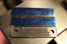
But the wear on the shoe was a concern. I had located some high quality 2mm thick Phosphor Bronze sheet stock, and proceeded to make a pair of replacement plates. I believe the reason they call these adjustment plates because the original models actually had a taper to them that allowed you to slide them to adjust the gap, but these are just flat plates that seem to be harder than the shoe based on the wear. So me calling them wear plates is kind of sarcastic since instead of being sacrificial, they wear a much more complex, expensive and hard to replace part...

plates.jpeg

These plates are mounted on two 4mm pins, they are 10mm x 44mm with the holes 5mm from the edges. Interestingly the front hole is 4mm and the rear one is 4.1mm, which I think was intentional as it would otherwise be overly constrained and a pain to assemble or replace. I cut the rough strips out of the sheet, and was going to use my mini-mill to clean up the edges, but lately I've been trying to be smarter about overcomplicating things. Bronze is easy to work with and I had a lot of extra stock in case I messed up, so I decided to to just file it by hand instead. Since I had one hardened one still, I took advantage and used it as a file guide and to make sure I reamed the holes in exactly the same place.

template.jpeg

Drilling Brass and Bronze can be challenging because it is grabby, something that I quickly recalled when the first 2.5mm pilot hole violently pulled the part out of my vise. 😣 No real damage done though, I pecked like a starving chicken at the rest of the holes, going undersized with a 3.9mm drill. Then reamed the holes with a 4 and 4.1mm reamer (I knew that big box of odd sized reamers was going to come in handy someday!) Even with all my care, I still needed to hand fit the plates with a small needle file, but nothing too onerous.

new_plates.jpeg

Looking at the gap between the shoe and the new plates, it didn't look too bad... There were two adjustment screws, but no way was I going to try and flex a thin hardened steel wing that much. It would surely snap at anything but the smallest amount of deflection. So I pulled out the 'hero' unit and checked the gap on it, and it was very tight. "Hmmm, the old paper manual may have something... oh dear!" Factory specs are a miniscule 0.02mm gap, the Junker's was way more than that. The feeler gauges told the story, ~0.58mm. The plate I used was exactly 2.00m thick, and the factory plate was 2.08mm so I knew the new ones may need shimming, but that was a lot of space to shim. Further inspection showed that the unworn edge of the shoe was riding on the edge of the new plate, so I filed the plate about 0.1mm narrower so it would better contact the worn area.

Because the wear on that one side resulted in a sloped surface compared to the plane bisecting the spindle, I figured I would have to shim it at an angle to ensure good surface contact and prevent wear from being concentrated unevenly. Out of a desire to just confirm the right shim thickness, I put in a plastic 0.5mm shim, and frankly it seems to have just done everything I needed it to do. It is soft enough that it allows the plate to conform to the worn shoe, and seems to keep the gap and rotational deflection to basically zero. We'll have to see if it (and the much softer Bronze plates) hold up longer term, but I think these will be good fixes and may be worth replicating to revive the performance of a worn out unit if Biax doesn't answer your calls too.
 
Prior to working on the wear plate replacements, I took care of the deep cleaning. The motor armature has a unidirectional centrifugal style fan that draws cool air in through the rear of the motor and blows past the large deflection disk and through the 4 individual black plastic redirection units that point forward towards the front of the machine. Unsurprisingly this was far and away the filthiest of the areas so far, and everything required a lot of Simple Green and old toothbrush work. I mentioned initially that the power cord and switch looked too sketchy to test when it arrived, it was really bad. When removing the power switch I could see that one of the field magnet wires was fatigued to the point that it had almost severed, so it was the right choice from a safety standpoint to inspect and clean it. But it meant not knowing if the thing even worked, which was a little hard to resist hacking a quick test. But better to know that you won't damage something when the condition is so bad.

freyed.jpeg

The aluminum housing was colorfully, if not skillfully painted with I have to assume was some kind of nail polish secreted from a young girl. One side's lettering was filled in Pink, and the other side in Tiffany Blue. Yellow accents for the bottom adjustment text and the top where the user (I don't think it was an owner, I think these were issued to the workers) had crudely scratched their name into the top. The clownish colors and overall appearance made me think about what kind of guy this was, and wonder if his co-workers had taken the plate to spite him, or if he had removed it himself to make his machine undesirable to try and use. Anyway, acetone was the cure. I thought about sanding out the name, but I've become more tolerant of some 'character' (subtle Kanji joke.)

Back to the motor section, I removed the field magnet so that I could clean it and ensure there wasn't any metal contamination. Everything looked pretty good after cleaning, so I reassembled it. The speed controller, while not exactly potted, was painted in thick green paint (looked factory) and was dirty and rough. I sprayed it with electrical cleaner and it cleaned up well enough. The feel was very crunchy to turn due to the anti-vibration detents but when I compared it, it was similar to the Hero model. The switch was disassembled and cleaned. The thin rubber insulation sheet had worn through allowing a large amount of contaminants inside. The outer case was also cracked. Happily a new one is on the way from the Netherlands, but I was able to get this one working well enough to test.

strain.jpeg

The cord relief was as badly degraded as the cord. It came held on by 6(!) zip ties, I honestly wonder about people sometimes. This is the sort of thing that is really hard to find for me, because it's going to be called something inscrutable in Japanese and I have to do a lot of searching and looking for dimensions to find something appropriate. I settled on a plastic unit with a rubber compression grommet, I would have prefered something a little fancier or traditional, but functional will have to do. The hole in the housing was pretty much ideal for me to tap it with the M16 threads that the cord relief required. A little sanding of the plastic threads made for a secure fit.

Is it strange to have a go-to brand of electrical cord? I refurbish and build enough stuff that I have a favorite. It's made by Mitsuboshi (five star) SL2-TC Tough and is a marvelously durable, very rubbery and flexible cable that comes in various conductor counts and cross sectional areas. I keep 3 conductor 2mm on hand for the bigger tools, but the Junker is ungrounded (although I could have added one) and not a big load, so I ordered some thinner 2 conductor .75mm stuff and got a few spare Panasonic Tough-Cap plugs as I always seem to be out of them.

The last steps on the electrical was to replace the ferrules (got to get my money's worth out of those ridiculously expensive Knipex crimpers) and get the new cord securely in place. A light sanding and deep cleaning of the commutator bar and refitting of the brushes. It was as ready as it would ever be. With the new wear plates in place and oiled, it was time for first sparks, and it started right up. The speed control was smooth and linear, slowing it down to a crawl if required. No bad noises or smoke ☮️

gummy.jpeg

The final steps will be to make a new rubber pad for the spring shoe, and to swap in the new switch. The rubber pad is a pretty critical component from what I understand, so I wanted to make sure I got it right. I found the exact dimensions from a German website (its shape is more complicated than it looks) and a similar search established the shore hardness at 65, so I ordered some small 5mm thick rubber sheets in 60, 65 and 70 durometer and will carefully make a new one. I was going to rebuild the power switch linkage and print a new switch lever, but the hack they did works and actually doesn't bother me, so I'll keep it for now.
 
Great writeup so far. Daryl Smith posted a youtube video recently of a teardown of a 7elm. I was at his place a couple weeks ago and we were talking about the wobbler assembly - I don't he'd ever had one apart apart.

Would you mind posting the dimensions or a link to them for the rubber pad?

Thanks,
Mike
 
Would you mind posting the dimensions or a link to them for the rubber pad?
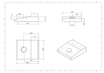
Ha ha, yes. I already made the model to allow people to print or make one themselves, I just need to create the dimensional drawing. Although I have one already, I didn't want to repost someone else's image of the dimensions for copyright reasons and links die. The rubber sheets came in this morning, so I will try to see how to best replicate the part. I fear that sanding is the answer... I'll post the drawing here, and the model on one of the 3D repositories (unless I can trick this forum software to accept it.)
 
I want to make a simple drawing for the wear plates as well, but for now here is the dimensional drawing. Don't blame me for the shape, it seems a bit overly complicated, but that's how it was presented in the original drawings that looked suspiciously like they came from Biax themselves. I want to print one up with the TPU filament I have, just to see if it is at all a reasonable approach, but my filament is harder at Shore 95A and I don't want to blow $40 on softer durometer stuff unless carving these rubber sheets is unsatisfactory.Biax+Rubber+Shoe+Drawing.png
 
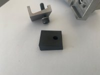
The printed part came out perfect. It's hard for me to capture a good photo a shiny little black piece of TPU, but I was impressed with how clean it looks to my naked eye. The slightly harder durometer of this material was obvious though, the factory part is softer than you'd expect, so I think something like Ninjatec Armadillo filament at Shore 75A would be a better match. It also occurred to me that this would be a very castable part out of liquid urethane. Anyway, let me try to make one out of the sheet without cutting myself.

print_shoe.jpeg

Daryl Smith posted a youtube video recently of a teardown of a 7elm.
I watched that, boy did I want to clean that poor thing. I noticed he has the motor rotated 180°, did he say why?
 
I want to make a simple drawing for the wear plates as well, but for now here is the dimensional drawing. Don't blame me for the shape, it seems a bit overly complicated, but that's how it was presented in the original drawings that looked suspiciously like they came from Biax themselves.
Your drawing looks like that one I made some time ago. The measures were taken from a new spare part.
Cheers,
Karl
 
Your drawing looks like that one I made some time ago. The measures were taken from a new spare part.
Cheers,
Karl
Yes, that was the drawing I pulled the dimensions off of! It was detailed enough that I suspected it was from the factory :giggle: I didn't want to deep link it or repost it without permission, so I made my own version, I hope you approve.
 
Last edited:
Okay, so I've embedded the STL model for the shoe in the JPEG image below. You will need to download the image and unzip it (yes, unzip the image file) to extract the STL. You will likely get a warning about padding, that's the actual image at the front of the file and can be ignored. I tested this and it worked for me, I can't promise it will work for you or that the forums will not do something to the file at some later point.

stl.jpeg
 
I mentioned that I got 5mm thick rubber sheets of 3 different durometers, just in case the Shore 65A number I found for the factory part was off, but it seemed close enough when comparing them. So I put a new blade in one of my Olfa's and carefully sliced out an appropriately sized chunk off of the 65A roll. It was very easy to cut, and even the large beveled edge I feared was doable with a very gentile sawing motion and a few passes with some sandpaper to flatten it out.

handmade_rubber.jpeg

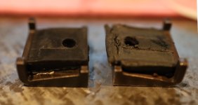
The new one is on the left, the printed one in the middle, and the clapped out one on the right. The hole was made by an appropriately sized drill, but being rubber it of course contracted. I have some hole punches that would maybe have done a better job, but I don't think it is critical and will remove excess material by hand if it turns out to be a problem. The original rubber was really well adhered to the blade clamp, so I used some flexible epoxy to attach the new one. Letting it cure for now, I feel like I'm getting close to the finish line, knock on wood that everything works as I hope.
 
Thanks for the detailed drawing of the rubber cushion, I made one a few months back but had to estimate the sizes. The rubber that I used was from a automotive suspension bump stop and quite hard at 75A Shore, although it seems to do the job quite well.
I cut a chunk out of the rubber stop with a hacksaw and squared up the outer edges by grinding on a surface grinder then mounted it in a shop made fixture to grind the 8 degree angle.


Biax Rubber Cussion.jpgBiax Blade Clamp and Rubber Cussion 2 (2).jpg
 
Last edited:
The replacement switch arrived from the Netherlands yesterday, and today I had enough time to disassemble the 'good' Biax to double check the wobbler tension screw arrangement, and replace the old grease.

new_switch.jpeg

The adjustment is really quite stiff, I wanted to make sure it wasn't from congealed grease like in the Junker, but as far as I can tell they keep it tight so it doesn't drift in use (as happened with the free turning wobbler in the rebuilt machine.) There were minor differences with some of the screws having different head types, I believe the good machine is a little older vintage, but it was clearly never used. I got really lucky. I replaced the old grease in the gearbox, using pure bearing grease on the bearings and Molybdenum type on the gears and the sleeve bushings and oiled the wobbler with ways oil. I also pulled some dimensions from the flimsy power switch linkage, as the switch hack on the battered machine works, but was unnatural enough in actual use to be annoying. I will try to model up a printable replacement.

I then pulled apart the Junker and easily swapped the switch. I tightened the wobbler nut, possibly too much, and replaced the cotter with a new one. I inspected the bronze wear plates and the bottom of the shoe, and everything looks good. Not a lot of hours on it yet, but I want to catch anything abnormal as quickly as possible. All the fasteners for the shoe to spindle, and the blade clamp were replaced with new Titanium socket head screws as the originals were worn and the slots badly marred. A little less reciprocating weight can't hurt either right? 🤓

I need to overcome my compulsion to 'do it right' and just try to do a quick hone on a few blades. Ideally I would have multiple grits for my Carbide grinder and some laps to do a final hone. But I only have a single wheel designed for my machine, and the other couple of wheels I've collected need to be adapted, and the honing plates need a magnetic mount designed and printed as well. I have a lot of blades that need to be shaped and sharpened, so it all is an intimidating project that has me a bit frozen in place. But tomorrow I will just try to brute force a single blade with the #400 wheel and see if it helps with the poor finish I've been seeing.
 
Ideally I would have multiple grits for my Carbide grinder and some laps to do a final hone. But I only have a single wheel designed for my machine, and the other couple of wheels I've collected need to be adapted, and the honing plates need a magnetic mount designed and printed as well.
This falls into the category of "off label use" or "not as intended", but in a pinch, I have put a 4A3-type resin bonded diamond wheel on my Baldor carbide grinder (which normally takes 6A2C-type wheels, 6" diameter with 1.25" bore) to sharpen scrapers. You don't get a honed or polished result, but at least you get a sharp edge (for as long as it lasts).
I've also made a couple of ductile iron (could not get cast iron in 6" diameter locally) laps in the shape of 6A2C wheels to use with diamond paste for honing. The Baldor spins faster than I would like for this operation.
I picked up some cheapish plated plates, but have not yet made an adapter/mount for the Baldor. I don't know that I will bother with a magnetic mount, as the plates have a bore with surrounding unplated area I can clamp on.
 
I retrofitted a VFD on the XB-74 Carbide grinder, so I have good speed control. It has a fairly standard 31.75 spindle nose, but the mounting screw pattern is a bit off from the couple of surplus Diamond wheels I've bought cheaply so far, and the new OEM wheels are $300-400 each, which I'm not willing to pay. I need to make an adaptor ring or drill a second set of holes in the hub to use them. The profile of the 125mm wheel gives plenty of surface to support those cheap thin Diamond disks, I just need to 3D print an interstitial part that I can put between the wheel and the disk that will keep it centered and locked in place.

grinder2.jpeg
 
In my opinion as well you don't need a lot of different abrasive grades. I also modified a carbide grinder to put a diamond wheel on one end and a lap on the other. I thought I might need progressive grit lapping plates, but in use I can rough to shape and do a rough sharpen on the diamond side, then go to the lap until all the diamond scratches are gone. It might take longer with a finer lap, but that's compared to the time taken to swap out lapping plates. It's crude compared to theory ideal, but good enough is perfect.
 
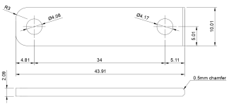
I have the measurements from the original wear plate in case someone needed to replace them and their originals were lost or damaged. This is from a used unit that I think was from the factory, but may be subject to wear or have been a homemade replacement, so I expect the tolerances for these parts are not super critical as seen by these measurements. The most important thing is to get the gap between the plate and the shoe correct, and I think the set screws in the shoe are a dangerous way to do that as the wings are brittle and are likely to snap off. Shims under the wear plates would be the better way to adjust this in my opinion (after snugging the set screws and loctite[ing] them to provide support, but no deflection.)

Biax BL40 Wear Plate.png
I also suggest that bearing bronze* be used as the shoes are much harder to replace and a hardened plate like from the factory seems to wear the shoe rather than the plate. Not ideal.

*Brass is not Bronze, it may work but it isn't what I'm suggesting to use.


Back
Top