Cal Haines
Diamond
- Joined
- Sep 19, 2002
- Location
- Tucson, AZ
This is a carry-over from a thread on taper attachments:
http://www.practicalmachinist.com/vb/monarch-lathes/taper-attachment-10ee-171651/index2.html
Since this is a bit off topic from the original post I'm starting another thread.
I recall reading about adjusting the nut on the crossfeed but I don't think there was very much detail on exactly how to do it. I worked through the process today and am writing it up so that the next guy will have an easier time with it.
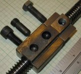
Here's a photo of the crossfeed ACME nut from my '43 round-dial:

To the right of the ACME nut is the drawbar clamp nut*, basically a T-nut with a radius machined in the bottom where it sits astride the crossfeed screw. The three fasteners associated with the ACME nut and the clamp nut are (left to right): crossfeed nut capscrew, crossfeed nut adjusting pin and crossfeed clamp bolt. These are my terms; the manual only names the pin, and I find its name confusing.
Here's a photo of the cross-slide with the compound removed and the three fasteners visible at the back of the top slide:

The basic procedure is to use the adjusting pin to push the front (operators end) of the ACME nut down, while holding the rear of the ACME nut up against the bottom of the cross-slide with the capscrew. This tips it down (rotating it clockwise in the first photo) to help compensate for wear of the nut. The procedure can be used to reduce or eliminate backlash (assuming that the screw itself is not too badly worn).
Here is a step-by-step procedure for adjusting the crossfeed backlash:
My machine has a one-piece ACME nut. The 1942 manual shows a two-piece nut, held together by four bolts, that uses shims to adjust for wear. This procedure would probably work for a two-piece nut as well.
Cal
* The clamp nut is typically only present in machines with a taper attachment and may not be present in newer (square-dial) machines with taper attachments. It's not clear how one locks the cross-slide without one. All of the cross-slides seem to have the third hole for the clamp nut and bolt.
http://www.practicalmachinist.com/vb/monarch-lathes/taper-attachment-10ee-171651/index2.html
Since this is a bit off topic from the original post I'm starting another thread.
I recall reading about adjusting the nut on the crossfeed but I don't think there was very much detail on exactly how to do it. I worked through the process today and am writing it up so that the next guy will have an easier time with it.
Here's a photo of the crossfeed ACME nut from my '43 round-dial:
To the right of the ACME nut is the drawbar clamp nut*, basically a T-nut with a radius machined in the bottom where it sits astride the crossfeed screw. The three fasteners associated with the ACME nut and the clamp nut are (left to right): crossfeed nut capscrew, crossfeed nut adjusting pin and crossfeed clamp bolt. These are my terms; the manual only names the pin, and I find its name confusing.
Here's a photo of the cross-slide with the compound removed and the three fasteners visible at the back of the top slide:
The basic procedure is to use the adjusting pin to push the front (operators end) of the ACME nut down, while holding the rear of the ACME nut up against the bottom of the cross-slide with the capscrew. This tips it down (rotating it clockwise in the first photo) to help compensate for wear of the nut. The procedure can be used to reduce or eliminate backlash (assuming that the screw itself is not too badly worn).
Here is a step-by-step procedure for adjusting the crossfeed backlash:
- Move the cross-slide to the extreme front (operator end) position. Backlash will typically be less at the ends of the screw.
- Tighten the taper attachment drawbar clamp and crossfeed clamp bolt.
- Loosen the crossfeed nut capscrew.
- Back the crossfeed nut adjusting pin out several turns.
NOTE: Never attempt of turn the adjusting pin without loosening the capscrew.
If the pin does not turn easily, remove it and chase the threads with a tap and die. - Draw up the capscrew. (This pulls the ACME nut up against the bottom of the cross-slide.)
- Turn the adjusting pin in until it bottoms out, don't tighten.
- Turn the cross-slide dial and note the amount of backlash.
- Back off the capscrew one turn (less when repeating the adjustment).
- Turn the adjusting pin in. Start with 1/4 turn, use more or less, as necessary on repeat. (This step pushes the forward end of the nut down.)
- Draw up the capscrew and snug it up. (This pulls the rear of the nut back into position.)
- Verify that the rear of the nut is in contact with the bottom of the slide. This will only be possible on round-dial machines, due the to longer slide on square-dial machines.
- Check backlash and repeat steps 9 to 12 as required.
- Release crossfeed clamp nut.
- Check backlash every inch or two across the length of the axis, repeating steps 9-12 to loosen the nut as needed, clamping the cross-slide at each adjustment.
My machine has a one-piece ACME nut. The 1942 manual shows a two-piece nut, held together by four bolts, that uses shims to adjust for wear. This procedure would probably work for a two-piece nut as well.
Cal
* The clamp nut is typically only present in machines with a taper attachment and may not be present in newer (square-dial) machines with taper attachments. It's not clear how one locks the cross-slide without one. All of the cross-slides seem to have the third hole for the clamp nut and bolt.
Last edited:
 These terms are often confusing when strangers get together such as on this forum.