What's new
What's new

Ampacity & Overcurrent Protection for RPC

venison

Plastic
Joined
Nov 15, 2016
I'm having some trouble interpreting Article 455... I have a friend who wants to run a 10hp motor (Name plate rating is 32-30.5A@208-220V) with a PL-20 RPC (https://www.northamericaphaseconverters.com/wp-content/uploads/2019/04/PL-20.pdf).

The instructions and specs given at the RPC website state: "Max Capacity Amperage of 50A" and a "Single Phase Minimum Circuit Size" of 50A.

He has an existing 240V/50A outlet that he wants to use as the power supply. If no other motors or loads are run other than the one 10hp motor, would the 50A outlet be sufficient to power the RPC and 10hp motor? And would the 240V be a problem for the 208-220V motor?

 
10 HP is 50A 230V 1 phase, per the usual UL table. And all the power is coming from that single phase source.

The sum of currents for both the RPC and the load will be pretty close even at low load. But it may work OK if the "10HP" is not a continuous load.

If it is a machine tool, it likely will be OK because it is not so common to run flat out to max power. Depends on the machine and how it will be operated.

The RPC will draw some current above it's idle current, since it will supply 1/3 of the load power. The load will draw the other 2/3 directly. Seems as if it will be pretty "close", depending on the actual load power. For 10 HP load, the RPC is probably a 15 or 20 HP motor.

I think it may be a good idea to put some power factor capacitors on the input to the RPC itself. That will cancel a good part of the idle current for the RPC.
 
My Phase-A-Matic 20hp rpc is run on a 125A circuit, as per mfr's recommendation. The spec's in your link say MINIMUM 50A/Maximum 100A. I found code and mfr recommendations don't always agree. I THINK you will need more than 50A. Voltage should not be a problem.
 
Last edited:
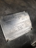
Sorry, the 10hp motor is 3ph and runs a Little Giant power hammer.
I'm not 100% sure how they work, but I believe the motor spins a flywheel which contacts the hammer mechanism by a clutch(?). If that's right, then I would guess the max load draw would be as the clutch is engaged... it has to overcome the inertia of the hammer, but then once engaged and running I'd guess the load would reduce some. Does that make sense?

It's funny, I have an ADX-20 in my shop; American Rotary calls for a minimum #6 to their panel, while the PL-20 calls for minimum #2. That's a pretty big difference... Seems like giving a "minimum" wire size like that is insufficient information from an instructional point of view...

Adding caps to this system is unfortunately above my ability level...
I was thinking that it would be cutting it close to try this on a 50A circuit, but I was also thinking that worst case, at least the conductors to the outlet are protected by the breaker, so in theory they shouldn't be allowed to draw enough to overheat and cause a fire, right?

The specs for the PL-20 says it pulls 7.4A at idle... I don't really understand the math to figure out how many supply phase amps the 10hp motor will be pulling through the RPC...
If we were to try it, I was thinking we may have problems tripping the 50A breaker, but other than that would there be any major safety violations?
 

Attachments

  • LGmotor.jpeg
    LGmotor.jpeg
    132.7 KB · Views: 5
Sorry, the 10hp motor is 3ph and runs a Little Giant power hammer.
I'm not 100% sure how they work, but I believe the motor spins a flywheel which contacts the hammer mechanism by a clutch(?). If that's right, then I would guess the max load draw would be as the clutch is engaged... it has to overcome the inertia of the hammer, but then once engaged and running I'd guess the load would reduce some. Does that make sense?

It's funny, I have an ADX-20 in my shop; American Rotary calls for a minimum #6 to their panel, while the PL-20 calls for minimum #2. That's a pretty big difference... Seems like giving a "minimum" wire size like that is insufficient information from an instructional point of view...

Adding caps to this system is unfortunately above my ability level...
I was thinking that it would be cutting it close to try this on a 50A circuit, but I was also thinking that worst case, at least the conductors to the outlet are protected by the breaker, so in theory they shouldn't be allowed to draw enough to overheat and cause a fire, right?

The specs for the PL-20 says it pulls 7.4A at idle... I don't really understand the math to figure out how many supply phase amps the 10hp motor will be pulling through the RPC...
If we were to try it, I was thinking we may have problems tripping the 50A breaker, but other than that would there be any major safety violations?
Disclaimer: I'm not an EE.

Your highest draw will be on start-up, and how long it takes to spool up the flywheel might mean you will need a bigger rpc, sounds like a "hard starting" application and you are pushing the limits.

Yes trying to compare rpc's is difficult, think some try to list minimum spec's so some folks think "I have a 50A circuit so this should work" :D

I think tripping the breaker will be first hint more amperage is needed, correct it after 2nd time or the price might get higher.

Edit: Might be able to use a single phase pony motor to get some speed into flywheel before applying power, its the dead stopped to XXXrpm that is going to suck the amps.
 
Last edited:
So even with supplying the RPC with a bigger feed it may still be undersized considering the nature of the load? hmmm, that could be a bummer.

It is a low rpm motor though... only 880... Doesn't that mean it has more torque per amp, and does that make a difference if RPC is big enough?
 
So even with supplying the RPC with a bigger feed it may still be undersized considering the nature of the load? hmmm, that could be a bummer.

It is a low rpm motor though... only 880... Doesn't that mean it has more torque per amp, and does that make a difference if RPC is big enough?
The operative word is "may", know anyone else running the same machine/motor? What size/mfr rpc are they using?

Yes, noticed the 880rpm on the data tag, no idea how that affects the price of tea in china, or amperage draw.....(pointing back at disclaimer in previous post)

Edit: Is the motor directly coupled to flywheel? Or is it belted to flywheel with a speed reduction?
 
Last edited:
I don't know anyone else with a similar set up.
I believe the motor is directly coupled to a flywheel but I don't know for sure.
Here's a pic.
Maybe could hinge the motor platform to engage belt/drive after motor is up to speed?
Would maybe smoke the belt a bit, but getting the motor running with no load on it I guess would be better right? I've never dealt with anything like this...
 

Attachments

  • LGHammer.jpeg
    LGHammer.jpeg
    132.6 KB · Views: 11
Ahh, a pic, worth a thousand words! Belted with a speed reduction, and the flywheel is not as heavy as I was imagining, thinking now you will most likely be ok. Try with the 50A breaker, if it trips do some re-wiring and go for the full 100A service.

Adding a tensioner so you can clutch the belts could work too, if they don't smoke too much.
 
Their no-load draw figure looks as if it already includes the power factor capacitors. A 20 HP motor as may be used on the RPC, would be expected to draw around 35A, at a power factor of perhaps 0.15. Given that all this is pretty much a (hopefully educated) guess, that shows up close enough to their amp draw to be credible for a power factor corrected unit.

Taking 25+ amps of draw off the source with the capacitors they seem to have installed already, is going to make a lot of difference.

That will take you from being "uncomfortably close" to being pretty much in the clear, from what I can see.

Also, a power hammer is a light load most of the time, with spikes of higher requirement during the stroke, and a little time after as the flywheel speeds up. That might have been OK even without the low idle current due to the capacitors.
 
thanks for all the help!
we'll give it a shot and I'll post the results.
ive got a 10hp on the same RPC. it works fine to run everything up to 5hp, over that if I run a 10hp on a 10 hp RPc the voltage drops out too low because there isn't enough current to support it. but it will start no problem on 50A
and voltage is usually plus or minus 5% ideally, some can be 10%. you will be fine.
 
Sorry, the 10hp motor is 3ph and runs a Little Giant power hammer.
I'm not 100% sure how they work, but I believe the motor spins a flywheel which contacts the hammer mechanism by a clutch(?). If that's right, then I would guess the max load draw would be as the clutch is engaged... it has to overcome the inertia of the hammer, but then once engaged and running I'd guess the load would reduce some. Does that make sense?
As in pounding hot steel from a forge. For knife making?

The 50A circuit/breaker and 50A motor is kind of living on the edge. Your startup current might cause trips.
If 50A is all there is then a soft start has to be done.
 
As in pounding hot steel from a forge. For knife making?

The 50A circuit/breaker and 50A motor is kind of living on the edge. Your startup current might cause trips.
If 50A is all there is then a soft start has to be done.

breakers that are in Good condition and have not been repeatedly run at very near their capacity
have a relatively long trip time for a medium o/l such as starting a motor, or suddenly loading a motor.
(which this breaker will be in about a year, [therefor i recommend replacing that breaker yearly]

breakers are built to trip due to two kinds of o/l's
1) just under to just over the listed amp rating :: this will cause a bimetallic strip to heat up and cause a trip over time: minutes to hours depending
2) way over the listed amp rating :: this activates a coil that will cause a trip immediately

breakers that have been tripped many times wear out and will do one of two things as a result
1) become harder to trip, and occasionally never trip (a good example is federal types from the US north west areas)
2) become easier to trip, this what most commonly happens to most breakers and brands

the primary thing you want to consider is the size/AWG and the temperature rating of the supply wire to the receptacle; especially if it is inside of a closed wall

NEC charts show #8 romex rated for 40A @60*C, and single conductor THHN shows #8 at 55A
if you have #6 romex (NEC = 55A) or single conductors in conduit (75A) your wire will never be a problem

most modern wires whether single conductors or romex cables are made with THHN insulation. it is rated for 90*C which is 194*F, near boiling. this increases the available ampacity of a wire compared to the same size of wire with lesser insulation values

which brings up another point about sizing the breaker to the load and then sizing the wire to the breaker
the NEC ampacity chart i mentioned also assumes that all breakers are rated for 60*C in an ambient of 40*C (ambient matters because of the bimetallic strip) unless stamped otherwise.
many brands of breakers are now stamped 75*C which means they can be sized to the wire at 75* rather than 60* ratings
the result of this is a smaller AWG wire is required for the breaker in some cases

if you really want to know what you have and the capabilities of it. look at 2020 NEC table 310.16


Back
Top