What's new
What's new

Another Lost Art 3 Points

Richard King

Diamond
Joined
Jul 12, 2005
Location
Cottage Grove, MN 55016
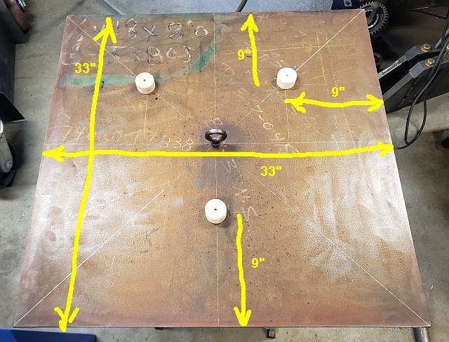
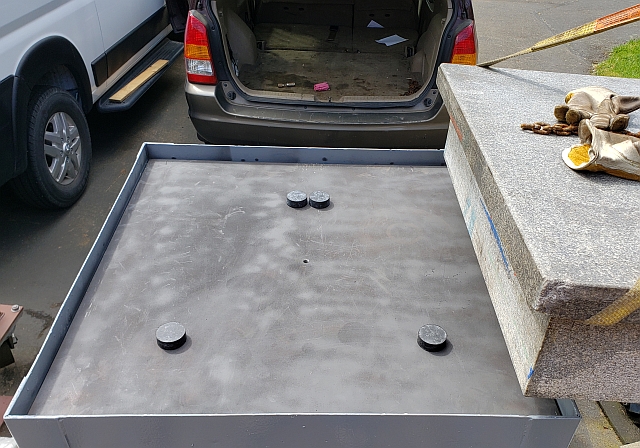
Many rookie scrapers never use a 3 Points while scraping machine parts. They forget how cast iron bends due to its own weight and gravity. They take a mill table off and lay it on a work bench upside down - T-slots down and start to scrape the table flats. They will blue up on the ends, they scrape it and when they match fir it to the saddle it never fits right. Because they didn't put the table on 3 points before they scraped it. Have you ever wondered why Granite surface plates set on 3 points? Or why a Moore jig Bore sets on 3 points?

Why a Monarch EE lathe sets on 3 points ? It's so they take the chance of twisting out of the picture. For those who want a "paper on this" they can look up The Kinematic Mount Principal. My friend Professor Alex Slocum of MIT has written books on it. It is a Lost Art. I am sure the old timers who were trained machinists use it when they mill or grind parts up and block around them when the part is not flat. They set it on 3 points to "eliminate a twist" that can be created when a crocked part is clamped or magnetic chucked down it bends down and you mill or grind it. It is milled or ground and when it is released it bends back to where it was, bent. If it is milled or ground when on 3 points and not clamped it doesn't bend and comes out flat. This is what I do when I scrape parts.
 
The questions are, where should those 3 points of support be placed and how is the part secured? I'd guess that you would target the "points of minimal sag", but surely on a complex part that isn't a simple calculation. I'd worry that badly placed points would be worse than a fully supported workpiece.

Can you show us some examples of the fixturing you've used and the methods to choose the support points? Are these points sometimes present in the parts from the manufacturing stage? How are they identified?

Securing that part when it is balanced on three contact points seems difficult as well, as you would need to put any clamping forces directly over the points of contact, otherwise you are just going to deform the part further. I can picture an arrangement of 3 switchable magnets which would provide both support and hopefully enough grip to allow for scraping, but seeing how you do it would be really informative.
 
There is no real need to "look up papers" to understand the importance of proper surface plate support and to estimate how much deflection it might cause to not follow the rules.

A "simple beam" calculation allows an educated estimate of how much a granite surface plate 36" long and 6" thick would deflect if supported only at its extreme ends. Based on such a calculation (provided I did not make some silly error) such a surface plate would deflect at a max at its center .00012 due to its own weight. And if you placed 200 pounds dead center it would deflect an additional .00003 (3 one hundred thousandths).


I think it is useful to know how much deflection might occur to help assess whether slight variation of support location might make a significant deflection error. It should not.

The standard flatness for a 36x36 Grade AA surface plate is 200 microinches of overall flatness. Or .0002"

Here is the beam calculator I used though there are many available:
Beam Deflection Calculator

Here is table of tolerances allowed for granite surface plates that I used:
https://www.mitutoyo.com/webfoo/wp-content/uploads/15004A.pdf

So, the conclusion I am drawing is that the worst possible case of improper support would cause some deflection of a AA plate degrading it to still better than an A grade. Would I recommend such careless support? No way since a good approximation of ideal support is so easy. But again, in my mind it is helpful to understand what the "rule" means and how much error might occur should you need to deviate from it for some practical reason.

The above relatively low degrees of deflection are consistent with some careful measurements of my own surface plates that I and a fellow PMer made in my shop using his fancy equipment. (His hobby is measuring equipment like electronic levels, autocollimators etc.) He found that myu Grizz surface plates would qualify for AA flatness though they fail to make that grade as the 24X36 is only 4 inches rather than 6 inches thick. The same was true for the Woodcraft 12X18 plate I own. Both were quite cheap. Both are very good. That experience is also consistent with some measurements made during a scraping class I took 10 years ago where the instructor bought a couple "Chinese" surface plates and checked them out during class. They were extremely good.

I apologize in advance if I screwed up the calcs---not impossible. And will welcome correction of said miscalculations.

The same calculator linked above could be used to make a fair estimate of mill table deflection under various support conditions though the complexity of the cross section would make calculation to five or six decimals a bit tricky.

Denis
 
But I believe Mr. King is not talking about just the surface plate, he is saying the workpiece itself should be supported on three points. The question I'm asking, is if this is the optimal way to scrape a part, how would you best determine the support points?

To be fair, I don't think he is saying that full support by a surface plate would be problematic (magnetic chucks and clamping may induce unwanted deflection though), but sitting the workpiece on a "workbench" that has a non-calibrated surface could induce problems. But is 3 point support at the roughly estimated "minimal sag" locations better than full support by an uncalibrated surface? Or is there a more precise way to determine the optimal support locations?

I understand Mr. King mentions a white paper on the subject, but as he indicated that he uses this 3 point method I was asking for some hints on how he's determining the points in his work.
 
There are "minimum deflection" points of support for things such as rods, and perhaps straightedges.

The 3 point support idea is that three points define a plane, and thus each support must therefore carry part of the load. With, say, 4 points, the loading is statically indeterminate. You cannot use the dimensions of the support locations and determine the load on each, but you can do that with three points.

One issue with three point support is that the ends are different. At one end, the two points of support may be at the minimum deflection points for the "width" of the plate.

However, at the other end, there is only one point of support. So the result that might occur with a flat plate of approximately uniform thickness is that the end with one support has an overall "bow" to it, with the unsupported corners sagging. The end with two supports would sag a little at each side, but also in the middle between the supports. That end would have the least difference of the deflected shape from a straight line, where the end with one support would have considerably more.

There are good arguments for three point support. For one thing, it allows the part to take the shape it wants to, at all times, so that any stress relief ends up being compensated out in the scraping. You are not forcing any particular shape onto the part, only gravity is affecting it..

However, there is a decent argument in favor of supporting the part just as it is supported in the machine. After all, that is how it will be used.

If the part is used when supported in the same way as it was when it was made flat, it should be the flattest in actual use. The position and support in the machine may tend to force a shape onto the part that is not in accordance with what shape it would take "naturally".

However, if all parts are allowed to be in their "natural" un-stressed conditions when they are scraped, then they should also be in their "natural" condition when assembled. Or, perhaps a better statement, their "natural" condition would be such that all the other parts (also in their natural condition) would fit them perfectly.

It is an interesting question.
 
However, there is a decent argument in favor of supporting the part just as it is supported in the machine. After all, that is how it will be used.

This is an important point. The granite plate and machines that Richard uses as examples are supported on three points because that is a repeatable support that does not (cannot) impart unpredictable internal stresses to the structure. But it does allow gravity to do so. Because the effect is repeatable, however, that’s okay and is calibrated out.

A machine part that is supported in one way to be scraped or machined and in another way when used is an invitation for error. So I don’t think it’s correct to say that it’s always best to support a piece on three points for scraping/machining. That will be repeatable but not necessarily representative of how the piece is used.
 
So, your point is well taken, JST.

Just to a gross approximation I did a beam deflection calculation on my Bridgeport table. Its dimensions are roughly 9.5W x 3.5H X 42L. Accurate calculation of its moment of inertia would involve a fair bit of work given the t-slots and dovetails involved. So, I ignored them hoping for a general idea of expected deflection. I got .0018" deflection. In reality the table would probably fare a bit better due to the lightening and improved moment due to the slots and v-ways.

But the problem of how to support it while working on the V-ways is interesting. How does one approximate the bend in the table? I guess by inverting it and placing it on blocks with one at each end of the table. You mark it out and scrape it. So now the table has a bow scraped into the V-ways. Now you have to scrape the top. You would want the arc of the top to be parallel to the arc of the bottom I would think. How exactly do you accomplish that? Supporting it on its center would bow it the other way roughly in a similar arc to the V-way arc. I guess you could confirm the arc shapes were similar on the surface plate using a surface gage and dial indicator. Hmmmm.

And, if the assumptions I made above are wrong, please, someone, set me straight set me straight.

Denis
 
You are discussing the issue of "original straightness". When you get the part, nothing is flat, nothing is straight. Somewhere you have to get it straight for a reference.

Then you need to keep it straight for working on the other surfaces of the part.

I think then the minimum deflection support points come into play. And use of measurement of thickness to get one surface of the part aligned with another.

You can be certain that the result of ANY system will not be perfect. So you have to do the best possible.

If you get the top of the milling table flat, then you can put it on a flat surface (granite flat) to scrape the dovetail ways, because it already is flat. So it will not be distorted at all. You probably already scraped it to that flat if you have one. Then every operation on the other surfaces is done with the condition you want already in place. You will not scrape in a bow.

Why would you take elaborate care to put it up on three points, knowing that procedure will certainly and inevitably produce bowing that simply putting it on the flat surface cannot produce?

If you have no large flat surface to put it on, then you must fall back on the idea of using the support points for minimum deflection. They are located so that the maximum deviation from straight (flat) is minimized, taking into account the mass, moments, etc. Those points are known for simple shapes, and the mill table is actually similar to a simple rectangular block to a first approximation.

That will result in a surface that you KNOW is bowed down at each end, and also in the middle between supports. But instead of one big bow, it is three much smaller bows.

But what other choice do you have? I suppose you can do the thickness measurements, and scrape to them after getting it flat in the minimum deflection condition. That way you can perhaps compensate out the bow.

Of course, if the part you are scraping is worth anything as a design, it will be made so as not to be floppy and bow excessively in use, with work clamped on it. Or, at least as much as the designer could manage to do so (all machine design is a compromise). So the issue of bow, etc may be very small if you take care, since you are working on it when there is no work, no heavy vise, etc on the table.

Finally, there is the question of what accuracy you require. A well-made machine that does not bow excessively in use may likely bow far less when being scraped, as mentioned. The errors (you will never eliminate them) may be smaller than the overall tolerance you need to hit. A mill table is not a surface plate.
 
While teaching machine building in Taiwan several years ago at PMC - PMC I showed them how one has to find the balance point of odd shaped machine parts to determine where to place the 3 points. I also talked to my friends at Professional Instruments / Air Bearings Inc. Professional Instruments Company – Pursuit of Precision where we discussed the use of 3 points.

At PI they told me as a machine rebuilder I am working with rectangular shaped parts like a mill table, lathe saddle, cross-slide, etc. and outside a laboratory one can use 30% from the ends for the locations of the points. 30% from the outside edge on the 2 ends or under the ways and the center of the 30% from the other end. I usually experiment on odd shaped parts moving the single point where the gear rack fastens to a grinder table or where the hydraulic cylinder rod attaches. I assume the machine builders located those points to the center of weight. Over in Taiwan we scraped VMC columns that used scraped ways or where linear ways attached. For the most part VMC columns are a Triangle shaped and are not rectangles. We would set the triangular shaped column on a a 2" steel shaft and move the column on the shaft to find the center of gravity so it would balance,

From that location we would place the 2 points on the wider end 1/2 way from that center point to the end of the wide end and then place the single point 1/2 way from the balance point to the thin width end. PMC had several ways to test these location (Granite plates, lasers, precision levels, etc. and we did research on our educational research we taught the machine builders. That way deflected the least.

I also taught several classes at QUASER MACHINE TOOLS, INC. and they originally had issues with their machine castings changing when they machined and scraped machines. What I did was to tour the plant from the warehouse where they stored the castings of their machines before they machined them first, they moved them to the assembly floor to built the machines. I discovered they would receive the castings from the foundries and heat treaters and set the parts in the warehouse either directly on the floor or on wood blocks placed in any location.

I had them start to use 3 points on all their casting inside their warehouse to store those castings. Then use those 3 points when machining and assembling them. When I taught at https://www.ycmcnc.com/en They started to cast the 3 points into their castings so they didn't need to use wood block during storage. That is what Giddings and Lewis use to do the the columns of their HBM's.

Teaching machine building and machine rebuilding for over 40 years from things my Dad taught me and discovered on my own is what I am so proud of. I have received awards from machine builders and rebuilders for my help improve their processes. Here are a couple of references I am very proud of.

"Ever since you instructed our first group of rebuilders, we have had numerous requests to have you back to instruct the remaining rebuilders. Your ability to adjust your class to fit our needs left a lasting impression.

Even though our rebuilders are experienced at scraping, they learned new techniques to improve accuracy and efficiency. The rebuilders had a lot of praise regarding the class and recognized your expertise as you worked along side them.

I strongly recommend King Way ... seminar for instruction in Basic 40/40 Hand and Advanced Machine scraping. It is excellent for anyone who is doing machine rebuilding or slide retrofitting."

Norm J.
Supervisor Machine Rebuild • TIMKEN • Canton, OH 44706
____________________________________________________

"Machine tools are the basis of all industrial production. Neither car industry, medical health nor aeronautics could exist without precise machine-tools. And you should supply these precision factors with perfect scraping and alignment.

King Way has proved to be a most reliable and effective member of the scraping methods at our company. Our workers have learnt right technique of scraping and have been a good member of known power and hand scraping.

I strongly recommend King Way. It is excellent for anyone who is doing machine rebuilding and production machine tools. I would gladly answer any request for further information about King Way."

Muharrem S. ERBERDI
Assembly / Mechanical Engineer • Spinner Machine Tools Co
Spinner CNC Takım Tezgahları Fabrikası

IMG_3970.jpgIMG_3971.jpgTami award 2.jpgTami award.jpgIMG_1407.jpg
 
Don't mean to hijack this thread, but I have a surface plate 3 points question.

I bought a used surface plate. It is 36x36x8" and has a stand. The plate has 4 ledges. The stand has 4 sides and a lip inside the top where the plate sits. Ignoring the ledges the plate is 33x33x8". This is the part that fits down into the stand.

The plate sits on 3 points but they are the wrong 3 points. There are 3 flat pads around the inner lip that the plate sits on. One is halfway across one side and the other two are in the far corners of the stand. None is inset at all.

I want my plate sitting on 3 points as specified in the Federal specification which says each foot is inset between 1/4 and 1/3rd the length of a side (assuming the plate is square). I cut out a piece of 3/8" plate and set it up to work on it. The lifting eye in the middle is so I can pick it up with an overhead hoist and set it down into the stand.

I mocked up where the 3 feet are going to go. Each is inset 9.5" from the relevant edges. I placed round slugs of plywood where the rubber feet are going to go. (I decided to put the feet on the stand and not glue them to the surface plate since working with a 900 pound chunk of granite is a lot harder.) This is what my 3/8" plate looks like now:

standInsert.jpg


So what am I writing about? The foot locations just don't look right to me. I've done the math 20 ways from Sunday and it always comes out OK. So I thought while I'm waiting for my threaded rubber feet to come from McMaster that I'd ask you guys.

Do these seem right to you?

metalmagpie

No. Airy points for a rectangular plate would be 1/4 to 1/5 of the 33 inch dimension. So 33*.22≈7.26 from both edges and in 7.26 from the end, with third point centered and at 7.26 from that end.


Sent from my iPad using Tapatalk
 
No. Airy points for a rectangular plate would be 1/4 to 1/5 of the 33 inch dimension. So 33*.22≈7.26 from both edges and in 7.26 from the end, with third point centered and at 7.26 from that end.

Ah HAH! The copy of that spec I read had a typo in it. In the paragraph it said between 1/4 and 1/5th like you said, but in the image it said 1/4 and 1/3. Hence my mistake.

Nice catch!

It will look a lot more like I thought it would if everything moved out a bit.

Are you still in Kirkland?

metalmagpie
 
According to Starrett:

[FONT=&quot]“A) A surface plate should be supported at 3 points, ideally located 20% of the length in from the ends of the plate. Two supports should be located 20% of the width in from the long sides, and the remaining support should be centered. Only 3 points can rest solidly on anything but a precision surface.[/FONT]
[FONT=&quot]The plate should be supported at these points during production, and it should be supported only at these three points while in use. Attempting to support the plate at more than three points will cause the plate to receive its support from various combinations of three points, which will not be the same 3 points on which it was supported during production. This will introduce errors as the plate deflects to conform to the new support arrangement. All Tru-Stone steel stands have support beams designed to line up with the proper support points.[/FONT]
[FONT=&quot]If the plate is properly supported, precise leveling is only necessary if your application calls for it. Leveling is not necessary to maintain the accuracy of a properly supported plate.”

Denis[/FONT]
 
Flip the plate over so we can see what the bottom looks like. Some plates are not made to be used as an inspection plate. They are called "bench" plates. I suspect this is a bench plate if the MFG. used 4 feet. Look at page 3, top right. Also some Inspection cast iron were machined, ground and made to use as a surface plate that is never flipped over. It sets on a stand and used for inspecting parts sitting on them. Others are designed to be flipped over and rubbed on mill or jig bore tables. Those types of plates have deep ribbing on the bottom. So lets flip your plate over and see what your working with. Using the Granite Federal specs for a cast iron bench plate is not what we use.

http://www.buschprecision.com/Busch-Precision/PDFs/Marketing-Materials/BuschCatalogWeb.pdf
 
Ah HAH! The copy of that spec I read had a typo in it. In the paragraph it said between 1/4 and 1/5th like you said, but in the image it said 1/4 and 1/3. Hence my mistake.

Nice catch!

It will look a lot more like I thought it would if everything moved out a bit.

Are you still in Kirkland?

metalmagpie

No. I’m in Oregon right now. You would’ve loved the AA two ledge plate I sold to Josh. With factory stand.


Sent from my iPad using Tapatalk
 
Flip the plate over so we can see what the bottom looks like. Some plates are not made to be used as an inspection plate. They are called "bench" plates. I suspect this is a bench plate if the MFG. used 4 feet. Look at page 3, top right. Also some Inspection cast iron were machined, ground and made to use as a surface plate that is never flipped over. It sets on a stand and used for inspecting parts sitting on them. Others are designed to be flipped over and rubbed on mill or jig bore tables. Those types of plates have deep ribbing on the bottom. So lets flip your plate over and see what your working with. Using the Granite Federal specs for a cast iron bench plate is not what we use.

http://www.buschprecision.com/Busch-Precision/PDFs/Marketing-Materials/BuschCatalogWeb.pdf

Rich, the stand did support my plate on 3 feet, but the 3 feet were not correctly inset from the edges. I have fixed that now. See the pic:

properFeet3Point.jpg


OK, I know there are really 4 rubber feet, but that's the way Starrett does their plates so that's the way I did mine.

I got the plate onto its rebuilt stand and hauled it out to the last guys who can relap a granite surface plate in Western Washington. When these guys retire they intend to close the business and after that if a Washingtonian needs a plate lapped, it will have to go out of state.

metalmagpie
 
@Richard King I know this is not for machine rebuilding, but I saw a point about 3-point support in a video and it reminded me of this thread. A guy shows his small magnetic transfer blocks and points out that one application is supporting thin plates on a mag chuck for grinding, to avoid internal stress from the clamping:


Back
Top