What's new
What's new

Another New Toy

Fixing the Leadscrew Reverse

After almost a year of thinking I had all the problems with lathe taken care of, a new one cropped up last week.
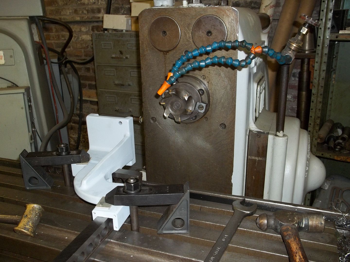
As is my habit with the CK and CY, the only way to reverse the feed and leadscrew is to shift the lever on the right side of the apron, I employed that method last week on the SE 60, for a facing operation. Much to my surprise, all I got was the dog clutch clicking, but not engaging. Completely forgot about the push-pull reverse knob lower down on the apron, until after I finished the facing. In between jobs, I investigated the problem, and Saturday morning I got into it. Pulled the covers on top of the gearbox and the lower headstock cover with the speed chart to expose the "external" parts. Couldn't get the reverse function to not work. I did find a spongy gear segment by forcing further movement and the small bevel gear not moving in relationship, it's pinned the same shaft. The big question, is how to get the gear segment and shaft out without taking the whole gearbox off. Save that problem for Monday.
Finally got back to the lathe yesterday afternoon, and figured out how to get the segment out without to much trouble. Take the snap ring off the top of the shaft over the smalll bevel gear, and get the taper pin out of the bevel gear, which is a lot easier said than done, and co-erse the shaft straight down into the gearbox, and hopefully not drop it, again a lot easier said than done. Finally teased it out. I was expecting to find a loose taper pin, pinning the segment to the shaft, but found a Woodruff ket and a set screw. There was a bit of movement, but not enough to account for what I saw earlier. Looked at the taper pin hole in the bevel gear, and it was oval, an ah-ha moment. Ream the taper pin hole in the gear and shaft to a larger size, for a properly fitted taper pin, and while I was at it, add a taper pin to the gear segment on the bottom, to really get this assembly nice and tight. Reassembled the gear segment in the gearbox, and the reverse shaft and gave it a test run. I still got the problem. I could force the gear segment a bit further, and the reverse function would work, but I'm not about to stand there with a screwdriver and the gearbox top off, while trying to run the lathe. Obviously, I'm missing something here.
Thought about for awhile, and decided to check the reverse gearing inside the headstock, to see if the shifter shoes were excessively worn.
Off came the headstock cover, with the forklift's help, and all was good inside. So what could it be? I did find the limits of the segment's travel, by looking at the dog teeth engagement inside. Tried different positioning of the detent bracket, and of the circular gear rack engaging the gear segment, and several other ideas, all to no avail. The only conclusion I could come to, was that the worm was a bit to long on one end, it's travel is limited by either the dog clutch inside the headstock, or the sides of the gearbox, and I couldn't tell which one it was, as I had already reinstalled the headstock cover. I opted to shorten the worm 1/16" on each end, and hope it works. It did, I can't force the gear segment in either direction.

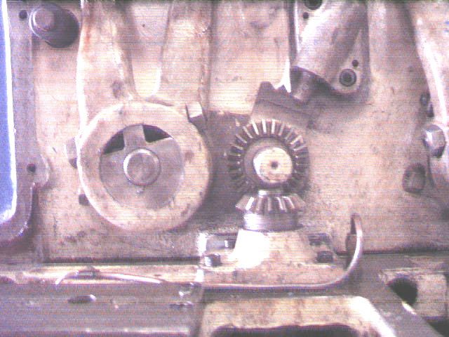
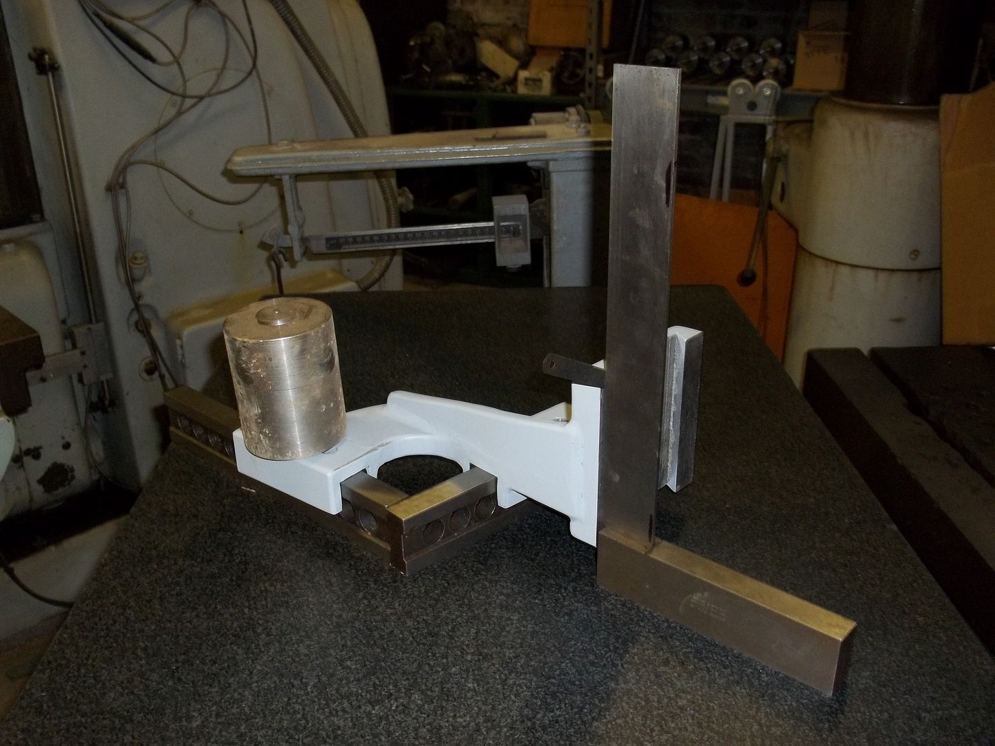
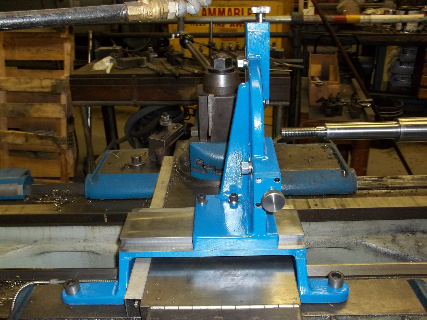
The bevel gear and detent for the leadscrew reverse. The center detent is neutral, the right detent is for left hand threads, and the plunger is not fully seated in the detent, and the left detent is for right hand threads.
se601.jpg


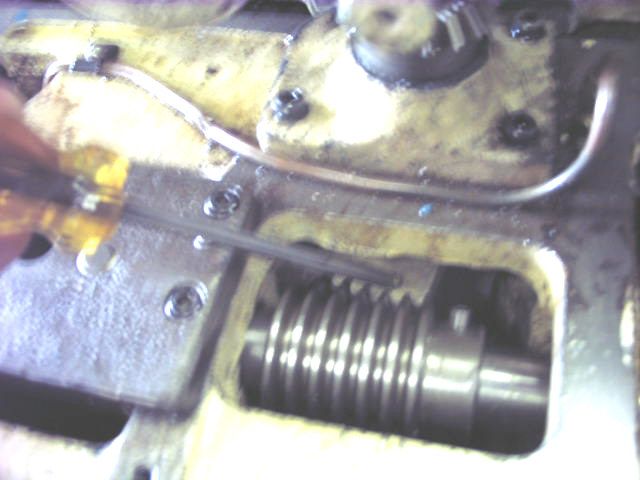
The ball driver is on the gear segment, that is compounded to the small bevel gear in the previous picture. The circular rack is pinned the reverse shaft, and on the left is the nut block, in which is the 4 start worm pinned to the shaft. In case you are wondering, when the reverse shaft is in neutral the worm can be freed from the reverse shaft by unscrewing the threaded dowel and teasing it out.
se602.jpg


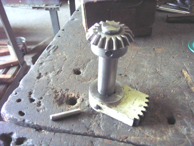
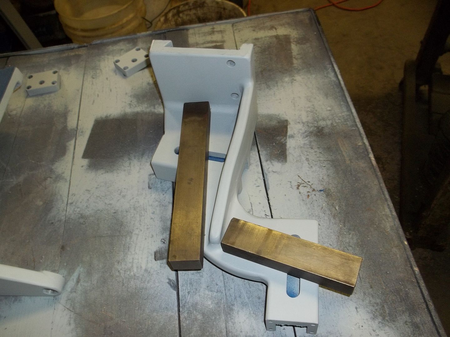
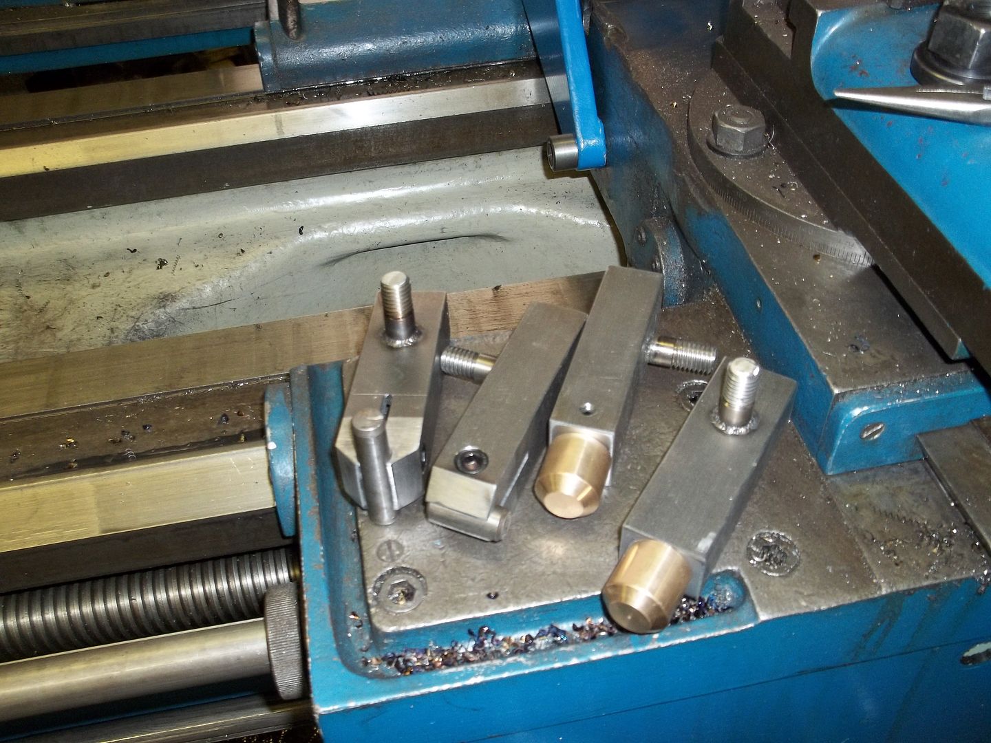
The gear segment and the bevel gear. The taper pin on the table is for the bevel gear.
se603.jpg


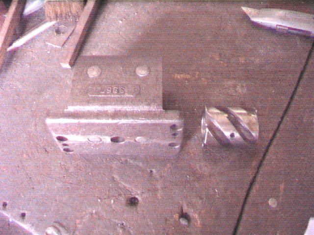
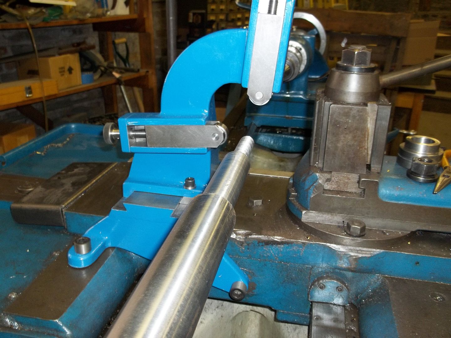
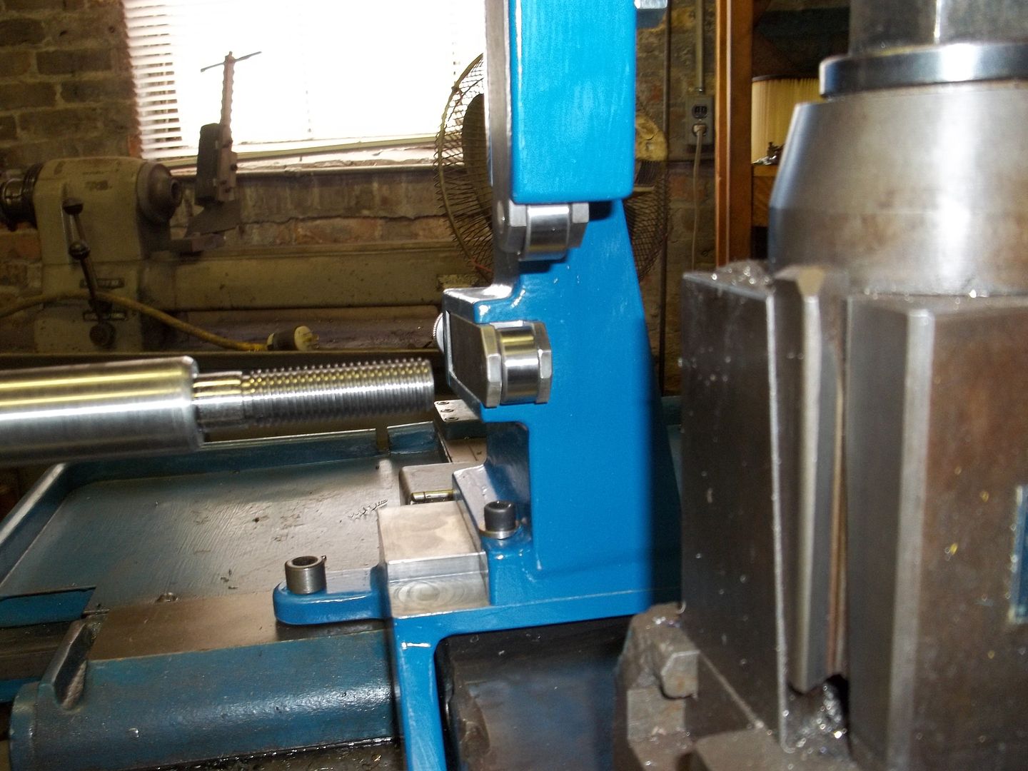
The nut block and 4 start worm. You can see the pin hole for attaching the worm to the reverse shaft. In this picture, the worm has alredy been shortened. The worm gives axial movement to the reverse shaft.
se604.jpg

Harry
 
Now that you have had a year of use of the scraped surfaces, could you please post some photos of how they now look?

Do you find that the Multifil has a rapid initial wear in on freshly scraped ways, or does it all stay pretty stable.
 
The wear rates on the scraped surfaces, or any other surface, will be dependent on; how much use the machine gets, the lubrication, and the cleaniliness. The SE 60 in this topic has not seen much use, although I am slowly working it into flow of work. This does not give much information about the questions you asked; however, I do have long term experience with other lathes in my shop that have had the same procedures applied to them. I have not noticed anything that suggests investigation, or gives me cause to think of changing the procedures used.
Monarch lathes have a built in automatic lubrication pump in the apron, which, IMO, is a very large plus in reducing the amount of wear in all of the bearing surfaces that are serviced by this pump. In other lathes, that I've reconditioned, that don't have the pump, the story is a little different, especially over a period of years.
Harry
 
Thanks for the prompt reply Harry. You reconditioning threads are inspirational.

You make it sound easy to scrape in a saddle while controlling front to back and side to side tilt, and the cross slide perpendicularity.
Mark
 
WOW! Awesome write up! I should get you to come out and help me do a good inspection on my CBB someday. I can barely comprehend some of the checks you perform. I just know turn, check diameter, turn some more until it is right. I like to think I have everything set correctly and that everything is working like it should, but sometimes I wonder about the oiling system. I don't have anything to comparre it to so I just assume since it leaves oil on the ways it must be working right. Your write up on the DRO installation a long time ago did inspire and help me to install one on my lathe. It certainly made my life easier. I can trun my camshaft blanks in a 1/10th the time it used to take doing it all manual with calipers and dial indicators and tons of mag bases. Keep up the good work.
Brian
 
Harry, boy do those parts look familiar. You can see the same designer's influence on the 60, round dial 10EE and square dial 10EE, all for similar tasks. The worm is like the one used for round dial ELSR, the partial sector gear is like the one on the square dial ELSR.

-Dave
 
The Follow Rest

About a week ago I posted a new topic, it's linked here, that I will continue here, where it belongs.
http://www.practicalmachinist.com/vb/monarch-lathes/test-picture-follow-rest-219714/
The FR pictured above and below, with the exception of some fine tuning is complete. There are some design and assembly changes I would make, were I to do this again; I would locate the clamping on the rear of the top slide to make the clamping easier to do, and I would put reference lines on some of the pieces to be welded before welding, to avoid positioning errors. If you look closely, the left side bridge riser is slightly out of place, and the mounting holes are off center. The entire FR is made from hot and cold rolled steel. I included slots and reference edges on the critical pieces to help insure alignments. In an effort to minimize weld distortion, I used 5 clamps to locate the top 4 pieces in position prior to welding. There is a picture with the clamp bars in place, in a re-creation attempt. This came out, surprisingly, relatively flat. All butt joints were champfered for welding, and ground afterwards, hence Russ's "chrome".
The jaws are 100* apart, starting at 5* under horizontal, the capacity is approx 1/2" to 4-3/4", although I don't think I'll ever get past 3"'s.
Those are the highlights, time for pictures.

Checking for squareness of the weldment. Of course I would think of this after priming. It's hard to see, but there is a .012" feeler gauge between the square and the top.
100_0006-1.jpg


Set-up on the horizontal for milling the bottom square. I also had to do the dovetail section.
100_0007.jpg


This is the partial re-creation of the weld clamping. The welder did long tacks on each side before the clamps were removed, and the welds completed.
100_0008.jpg


The next 5 pictures, for show and tell only, are on the lathe. The lathe is set up for a job. The pictures are pretty much self explanantory.
100_0009.jpg


100_0011.jpg


100_0012.jpg


I made up 3 sets of jaws, bronze tipped, roller bearing, and what supposed to be carbide tipped. I haven't located the 1/2" D X 1" long carbide yet, so I'll use dowel pins instead. The pins in place are for show, and will be replaced with the proper length dowels, or carbide, whichever comes first. The roller bearing jaws have .1 MM shims on each side of the 5200 sealed double row bearings, as spacers.
100_0013.jpg


100_0015.jpg

Harry
 
Just bought an old Monarch series 60 (13 x 30)...good price, pretty rough shape.
This thread will be my guide. Thank you SO much!
 
whats the idea with the carbide tips and how did you drill the hole in the carriage? is it blind? as its made out of steel, does the fr ring?
 
The carbide tips are for wear resistance. The holes in the saddle were drilled with a electric hand drill, and they are blind. The FR does not ring, in my experience, but then again I hardly ever use it. I can count on both hands how many times in the past 30 years that I've used a follow rest, but when you need there simply isn't any other choice.
BTW, the last time I saw this lathe was 11-18-11, it was sold at auction.
Harry
 
The meter units may be leaking at the manifold, but it's pretty hard to tell. They are passing oil at a respectable rate, at least the ones I could see. I did have to change one from a 00 to a 0, today, on the gearbox system. There are 2 lines that go into the "bowl", one oils a bearing and the other is for the gears. I could see some tell tale traces from the bearing, but wasn't getting anything out of the gear tube. That unit got changed, and things are better. I was able to get the suction end of the pump covered without totally filling the gearbox.
The Bijur meter unit has a radiused end on the inout, that I think acts as the compression seal, the "Trico's" don't and I think that may be the cause of the leakage problem. I think an easier solution to that leakage problem would be to put some pipe dope on the threads.
I think I've got seal a problem on the pump on top of the piston. IIRC, there is a very small O ring in there. I may investigate later.
Harry

Did you find out if the meters have an O-ring? I'm nervous I may be melting (or swelling) any rubber in mine since I have my headstock pump disassembled and soaking in lacquer thinner.

The gearbox pump is done, and flushing out the gearbox took 12 fills and drains before crud stopped flowing out. I used diesel fuel and kerosene. I thought I was done at around 5 flushes, and began to pour ISO 68 into the gearbox. Then a new section of crap broke free somewhere inside and the constant flow of floaties (or sinkies) started coming.
 
Thanks!

How noticeable should flow be on the sight glass that shows pump is working? I removed and cleaned all of the sight glasses...some were covered in paint! After flushing the headstock and refilling, I ran the lathe and the pump slowly flowed, filling the sight glass up to almost half. But after one week, it is starting to flow almost nothing (which is why I'm cleaning the pumps and lines). Is it supposed to be a slow sort of runny drip when working right?


Back
Top