What's new
What's new

Apogee

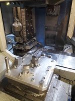
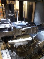
Well it has been busy these last few months, a lot on and never enough time. One of our main customer bases is historic race cars. Normally we get a bunch of broken or worn out parts and have to re engineer them back to their original state. This was a fun one, the back vertical bulkhead and engine mount off a Brabham BT49. No drawings available only the original cracked part. Spent half a day measuring it up on the CMM and drawing it, it was then machined in three operations out of solid.

20190911_181552.jpg
20190911_181610.jpg
CAD.jpg
20190918_185246.jpg
 
A new equipment day, well new to us. In order to run the laser with have to hold a number of 15 cylinder banks for nitrogen and oxygen purge gasses. Over the last few years this keeps adding up, combine it with the fact the supplier has reduced their delivery days to our area from 4 days a week to now Tuesdays we can find ourselves running out of gas. We either have to rent extra banks of gas which I guess the supplier is wanting us to do or the options we went with.

A set of three maxigas nitrogen generators, tanks and high pressure generators.
20191111_091348.jpg

First generator installed and being tested.
We aim to get 99.99% pure nitrogen from these.
20191128_193134.jpg
20191128_193117.jpg
 
Interesting.

So - is there an expected payback on the investment, or is it about the same cost with more independence as the main benefit?


----------------

Think Snow Eh!
Ox
 
Yes to both really. Being only able to get gas one day a week from a major supplier is ridiculous so this gives us independence as you say, it also fixes our running costs.

The generators use pressure swing adsorption technology, this works by separating nitrogen molecules from the oxygen molecules within the compressed air. Pressure Swing Adsorption does this by trapping oxygen from the compressed air stream using adsorption. Adsorption takes place when molecules bind themselves to an adsorbent, in this case the oxygen molecules attach to a carbon molecular sieve. This happens in two separate pressure vessels, each filled with a CMS, that switch between the separation process and the regeneration process.

Each generator uses about 40CFM which generates into the bank of white tanks this then passes through a HP compressor which takes it up to 35bar. The laser requires 20 bar of pressure. As our compressors run all day the generation cost will hardly register, the only increase will be running the HP compressor. At our current rate of gas usage we calculated that the set will pay for it's self in a year and a half. The laser currently runs 4-5 hours each day after set ups and material changes etc. Even if we were to run for double that time the system has enough generation capacity to keep up. The biggest savings is when cutting thick stainless and aluminium (10mm - 20mm)as the pressures and flow rates consume gas at a alarming rate and quite often makes these types of jobs expensive (We can use a 15 bottle 300bar bank in an hour) . Generating our own supply should make these jobs more competitive.
 
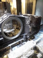
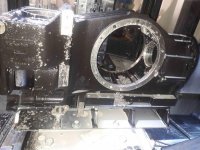
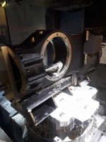
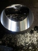
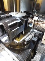
The latest fun and games are a set of magnesium gearbox cases. In order to get the pallet to spin with out hitting the end of the casing we had to take out the interchange door between the pallets.

These are done in three operations including a custom line bar tool that has to be hand loaded into the spindle to bore out the clutch shaft bearings.

20200110_152347.jpg
20200110_181053.jpg
 
Castings in lathes scare me :ack2:

Worst CNC crash I have witnessed was an iron casting being ejected from a giant Mori.
Ruined me when it comes time to chuck on a casting, LOL

Those shafts look awesome!
 
The latest fun and games are a set of magnesium gearbox cases. In order to get the pallet to spin with out hitting the end of the casing we had to take out the interchange door between the pallets.

These are done in three operations including a custom line bar tool that has to be hand loaded into the spindle to bore out the clutch shaft bearings.

View attachment 274973
View attachment 274974

Well that's interesting...
My pallet shuttle (index) is actuated from up top, so i'm sure that I couldn't doo that.

I can generally get away with an oblong/oversized part by getting it into Z- before indexing B, but if I have to re-home in the mean time - THAT can be a game changer!
I wish I could home each axis on it's own!


-------------------------

Think Snow Eh!
Ox
 
Thanks, Having a laser I have found it is very efficient to be able to cut out a few bits of 12/15mm plate, weld them up into the the rough shape and then finish machine the important areas. That was the second opp jaws. Opp one was to hold the casting on the outside of the barrel and turn the internal bearing bores that locate onto those jaws.

I do agree with you in not liking castings on lathes, It never feels like they are clamped and secured properly but when you have three bores held to 0.03 it beats having to set three boring heads and mill in all the lead in tapers, The RPM was clamped right down.

This is a Mazak 415 machine, all the lift and rotate functions for the pallet are under the castings with only a bolted pivot at the top so it takes about 20 minutes to get the door assembly out, the worst part is now stopping the coolant being fired out past the pallet doors while it is running, the last job we did this on we had a 2m housing mounted over both pallets which acted like a hose pipe.

You have what I wish I had on this machine, Z motion on the pallet. Being a 400mm pallet machine and the part is 650mm the door is only 75mm away from the pallet. I have enough room to index the pallets but then I can't rotate the B axis through the 90 and 270 degree positions. Pallet moves in X, spindles moves in Y and Z. The next generation of this machine switched the axis around so Z was on the pallet and you could do what you are suggesting.


Talking of crashes our Mazak SQT250 decided to knock a tool on the sub spindle chuck today. Control and encoder said that the B axis was home, tool came down 20mm behind the jaw edge. It turned out the toothed belt that dives the sub spindle ballscrew had partly split and allowed the belt to jump a number of teeth so in reality it wasn't really home. I can't get my head around why they would use a rubber belt for such an important function?
 
Will, nice thread and shop, and what a lucky buy on the CMM and cleanroom!

I'm curious about the magnesium castings, do you have a rough idea of cost per pound for something like the Lotus upright? Also, what alloys are used? I would think that there's no better place than England to get such parts made...

Do you ever work from mag plate, and if so, what alloy and price/lb (or kilo)? Not many easy sources for magnesium plate here anymore, and costs I've seen are quite high.
 
Their used to be a few places that cast magnesium but their is really only one option left over here that will cast these type of parts, it gets harder and harder to do.

The uprights are AZ57 and gearboxes RZ98. An upright costs around £250.00 to cast and they weigh roughly 1.1kg but some of the cost is due to pattern assembly etc. No haven't really done anything with plate, We have machined from a solid cast billet of mag rather than a shaped casting to save having to have patterns.
 
Well this gearbox case as been one of the most intensive things I have done to date, good fun but really gets you thinking with all the numbers.

20200119_185338.jpg
20200120_195041.jpg
Completing the first operation on the base and top of the casting. These lower features are used to position and align for the second operation.

20200126_142113.jpg
A weldment then had to fabricated and machined to bolt the casting on to.

20200126_162853.jpg
The casting set up for the second operation, this allows us access to all the remaining sides.

20200126_201927.jpg
First reference cuts to check size and that the part is where we think it is in the machine. All of this is programmed from the COR of the pallet.
 
20200127_205942.jpg
Starting to get the features in.

20200128_151104.jpg
Side plate location features for the diff.

20200128_181003.jpg
Almost all done.

20200128_194943.jpg
The most difficult part of the whole piece is the requirement to bore the three bearing locations for the main input shaft. To do this we manufactured a line bar to take the adjustable boring heads from Microbore, had it heat treated and then ground.

20200129_085930.jpg
Once the bar was tooled up each head was set 0.5mm short of the final dimension on the pre-setter.
 
20200129_161740.jpg
We also had to machine up a bushed plate for the end of the line bar, this locates on the same dowels that the bearing housing does and so sets the gear location correctly.

20200129_145423.jpg
Plate bolted in place.

20200129_164605.jpg
Line bar fitted into case.
 
20200129_165052.jpg
The assembly of the line bar is all programmed, so the pallets turns for you to slide the bar in then rotates around so you can bolt the plate on the back. The pallet then rotates back, aligns the spindle to the bore advances and orientates. The bar then has to be manually engaged into the taper before the control takes over again and advances the bar through the cut.

20200129_181150.jpg
Line bar in the middle of boring.


20200129_190831.jpg
Each bore has to be held to 0.02mm and 0.012 concentricity through the three bores.


Back
Top