What's new
What's new

Assembly Machining in SW CAM PRO

motofish84

Plastic
Joined
Feb 22, 2021
Hello,

I have been working in SW CAM Pro for over a year now running some prototype parts for my company.

We are a small manufacturing contractor and don't normally do much in the way of CNC machining until recently.

I have been doing smaller runs of parts with a single 6' vise and that has been ok. I want to utilize the "assembly machining" features available in SW CAM PRO to machine multiple parts on one setup however, I hit a couple road blocks last week.

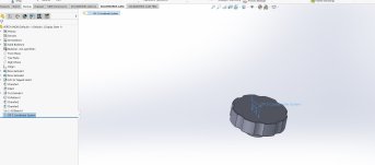
Normally when I have a part requiring multiple operations I will simulate op1 and save the completed simulation model as a .STL file to use as my stock for the next operation.

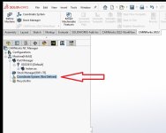
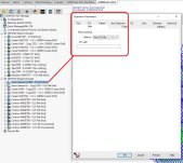
When attempting to use the OP2 .STL file as my stock in an assembly for each of the parts, the stock will default to the assembly coordinate system and not the locations of the individual parts. If I use a standard stock bounding box, the "stock" or bounding box will locate correctly and in relationship to each one of the parts. When using the .stl file, there doesn't appear to be any way to modify the coordinate system of the stock to correct this.

Any insight??

Also, wondered if some folks might be able to point me toward any decent training resources (VIDOES, books, websites etc) that has some detailed info on Assembly Machining in Solidworks CAM? There's a few videos online but none seem to address subsequent part operations and utilizing .STL files

Thank you!
 
When you save out your stock, you have an option to save it with whatever coordinate system you want. I don't remember if you have the option to select that same coordinate system when you pull it in, but it usually defaults to pulling it with whatever it was saved out in. So, if it's pulling it in with the Part's CS and putting it on the assembly CS, then just save it out with the assembly CS instead. The option for this is in the Save dialgue -> options(at the bottom), then select your CS at the bottom of the new window.

I remember having fun with this back in the day. It takes a minute to figure out.


Thanks for the reply @BluishInventor. You have helped me with SW questions in the past and I really appreciate you taking time to do so.

I went back to the OP1 Simulation and attempted to alter the CS. I do see the drop down for the output coordinate system however, the only option in the dropdown is "default"
 
Are all the parts the same? If so can you use patterning of the toolpath?

I don't use SWCAM I use HSMWorks, like it better, I do use Assembly machining all the time they do the same STL thing but I don't use it. I am pretty darn quick at modeling in SW, abuser since 1997, that I build my own solid for side2 and use that as my stock.
Again not knowing your part\s in the assembly hard to give a better answer to you.
 
Thanks for the reply @BluishInventor. You have helped me with SW questions in the past and I really appreciate you taking time to do so.

I went back to the OP1 Simulation and attempted to alter the CS. I do see the drop down for the output coordinate system however, the only option in the dropdown is "default"

I guess i should've elaborated a tiny bit more. You have to create another Coordinate System(the solidworks command), and then reference that in the dropdown.

Since SW CAM uses association with geometry -> feature -> toolpaths and the like, associating your CAM coordinate system with an actual SW Coordinate system is really important. Is it necessary? No, as you can select geometry to place and orient the CAM CS with points and lines. But having it associated to a SW CS, allows you to manipulate the CS via the SW CS without conflict and everything downstream(which is literally everything) will give you less trouble later on.

Ever had to 'rebuild' the CAM side and then it wants you to re-pick the CAM CS? If you create and use a SW CS instead of geometry, that's shouldn't ever happen.

With regards to stock, you may have to create an additional CS for re-use in another setup/config/program to achieve proper alignment.

Another habit to get into is create a folder in the feature tree called CAM. Place any CSs and geometry that you use cam side that isn't used for the model explicitly.
As @BluishInventor said, you have to create another Coordinate System and define it in your Operations Tree. This is key. I don't use Assembly Machining as much as I wish I did, there is a lot of benefits to Assembly Mode, even just programming a part on its own. There's a little more to setting it up than Part mode, and it seems to be a 50/50 chance I do it correctly.
It seems like if you have one thing off, it can mess up your whole set up definition from coordinate system to stock, from operation to operation. I've chased around CAM side being rebuilt and screwing up toolpaths, or coordinate systems moving because of a rebuild.
 

Attachments

  • Untitled.jpg
    Untitled.jpg
    85.4 KB · Views: 9
I agree with you, Marvel. I also wish I did more assembly set ups. I would get a more complete picture of what's happening. But I have to jump through extra hoops that trip me up easily. So I only do assembly when the work holding is real close.
Part set up is far quicker so that's my go to.
 
I agree with you, Marvel. I also wish I did more assembly set ups. I would get a more complete picture of what's happening. But I have to jump through extra hoops that trip me up easily. So I only do assembly when the work holding is real close.
Part set up is far quicker so that's my go to.
I have on occasion, programmed a part complete and opened it in Assembly Mode, set it in my vise, fixture, whatever it may be and imported the CAM data from Part Mode, you just can't have combined operations, you can, but when it imports the CAM data it for some reason creates duplicates of the combined operations.

My biggest issue when using Assembly Mode is a part that has multiple OPs, sometimes I can get it to let me program all sides in one machine definition, and sometimes it won't let me and I have to create a new machine definition. I can never decipher what I do different to get one to work and not the next. But in some cases I prefer to create a new machine definition, it gives me more control over previous machined stock using a STL stock file.
 
Still trying to get this to work...

I have created a separate assembly coordinate system and referenced it in the CAM ASSEMBLY. For the STL file that I want to use as my stock in the CAM ASSEMBLY, I created an "OP2 Coordinate System" that I am using as the output coordinate system when I save the STL. The STL stock is positioning itself at the ASSEMBLY CS that I created when I bring it in and does not allow me to reference the "OP2 Coordinate system" that I created and saved when saving the STL file in the drop down.

If I open the STL in my OP2 setup as a standalone part, it DOES allow me to bring it in with the "OP2 Coordinate System"

Scratching my head here....I know I'm close just cant seem to get a couple final pieces together.

Thanks for any help you all might offer.

Screenshots attached.
 

Attachments

  • SW KNOB SNIP.jpg
    SW KNOB SNIP.jpg
    231.6 KB · Views: 12
  • OP 1 Complete STL SNIP.jpg
    OP 1 Complete STL SNIP.jpg
    448.1 KB · Views: 12
  • SW ASSM SNIP.jpg
    SW ASSM SNIP.jpg
    345 KB · Views: 12
  • ASSM MACH - STL STOCK.jpg
    ASSM MACH - STL STOCK.jpg
    762.5 KB · Views: 10
Last edited:
Still trying to get this to work...

I have created a separate assembly coordinate system and referenced it in the CAM ASSEMBLY. For the STL file that I want to use as my stock in the CAM ASSEMBLY, I created an "OP2 Coordinate System" that I am using as the output coordinate system when I save the STL. The STL stock is positioning itself at the ASSEMBLY CS that I created when I bring it in and does not allow me to reference the "OP2 Coordinate system" that I created and saved when saving the STL file in the drop down.

If I open the STL in my OP2 setup as a standalone part, it DOES allow me to bring it in with the "OP2 Coordinate System"

Scratching my head here....I know I'm close just cant seem to get a couple final pieces together.

Thanks for any help you all might offer.

Screenshots attached.
Can you share the files?
 
A little update to this as I've worked around my original issue.

I took a class put on by Go Engineer that covered assembly machining in SW CAM Pro. With my new found knowledge I was able to work around my original issue by just using a stock profile that matches the area to be machined in OP2. Here it allows you to create a work coordinate system for each part to be machined but only with a SW Part file as stock or a general round or square stock profile. It doesn't utilize the .stl file as I hoped but it gets the job done. Also, none of the experts there could answer my question about how to use .stl files as stock when assembly machining with multiple part. That tells me there's not many do it this way and I should just do it the 'easy' way. It just helps to see the profile of the partially machined part but I can live with doing it the other way.
I replied to your email when you sent me the files. The other components didn't come through.

But it is possible to utilize the STL files. I am surprised they didn't know at Go Engineering. There's a couple ways to do it, but utilizing coordinate systems is key to getting the STL stock from a prior op to orientate right and be in the correct position.
 

Attachments

  • Untitled.jpg
    Untitled.jpg
    92.4 KB · Views: 3
I'll try and explain it as best I can.

How you programmed both OP's in Part Made with the configuration, wasn't wrong, but importing data into Assembly Mode doesn't import both "OPs / Configurations"

Programmed OP 1, simulated and save STL file to Coordinate System1, and be sure to select SAVE ALL STOCK IN SINGLE FILE.

In your CW Feature Tree, right click on your machine definition and COPY MACHINE. This will become your "2nd OP"

In your Stock Manager for this second op, Create Stock, Select your STL file and use the Insert Coordinate System, and select the same Coordinate System you saved the STL file to, this will align it correctly in XYZ
 

Attachments

  • Step 2 Copy Machine.jpg
    Step 2 Copy Machine.jpg
    156.1 KB · Views: 3
  • Step 1 OP 1 STOCK.jpg
    Step 1 OP 1 STOCK.jpg
    146.2 KB · Views: 5
  • Step 2-1 Machine Definition.jpg
    Step 2-1 Machine Definition.jpg
    144.9 KB · Views: 3
  • Step 3 Stock OP 2.jpg
    Step 3 Stock OP 2.jpg
    173.8 KB · Views: 3
I'll try and explain it as best I can.

How you programmed both OP's in Part Made with the configuration, wasn't wrong, but importing data into Assembly Mode doesn't import both "OPs / Configurations"

Programmed OP 1, simulated and save STL file to Coordinate System1, and be sure to select SAVE ALL STOCK IN SINGLE FILE.

In your CW Feature Tree, right click on your machine definition and COPY MACHINE. This will become your "2nd OP"

In your Stock Manager for this second op, Create Stock, Select your STL file and use the Insert Coordinate System, and select the same Coordinate System you saved the STL file to, this will align it correctly in XYZ
Interesting!

I realized that whatever CAM config you saved the original file in part mode is what data will import when you “import part data”

Going to have to mess with the .stl some more, there’s a step or two in there that I missed and I would prefer to use the .Stl representation of the stock.

Do you know how to get SWCAM‘s built in VF3 post processor to output local subroutines? (M97 instead of M98)

Thank you Marvel!
When I am programming in Part Mode, which is a majority of what I do. I create multiple Mill Part Setups to program a part complete. (See screenshot) This allows me to simulate a full part program. You can also simulate Operation 1, save that STL file and utilize it in individual operations in the following OPS. That way you aren't cutting air cause it thinks there's material there still that is already removed from OP 1.

Quick Tip on doing it this way and simulating, if you don't want to simulate OP 1 to get to OP 2 to see a full simulation, hold down SHIFT and right click on your second op set up and select simulate, a box will pop up, this is your WIP simulation, it will start the simulation at OP 2 but you'll be able to see the material removed from OP 1 - this also works for any individual operation, if you add an operation at the end and just want to simulate that operation with all previous material removed, you can.

Programming in Part Mode this way with multiple Setups in one configuration, allows for all Setups to import into Assembly Mode, but this is where Assembly Mode differs significantly, you are constrained to your WCS, it will import all operations, but you won't be able to Generate Tool paths for following operations that can't be "cut" based on your Z in your WCS. So this gives you the option to create another machine definition like I did above to show the stock, or you can bring in another set of parts, and flip them correctly based on Z orientation for a second or any follow operations, define the stock off STL files, etc. (See image) and you'll have both operations essentially in one Setup. This would allow you to sort tools throughout multiple operations and/or vises and combined set ups if you are running multiple ops in one machine at one time.

A big part of why I don't program very often in Assembly Mode is all the set up that is needed to get it to function correctly. You really have to know what you are doing and a big part of that is the Work Coordinate System.

As far as subroutines, I don't use them. When I am running multiple parts across vises on the same operation, in Part Mode, I tend to create a Configuration and just Pattern the full operation or copy the full operation into an additional set up and assign it a new WCS - G55, G56, etc and then I sort the operations by and across set ups.

A while back I played with subroutines briefly and had my post updated/edited to function correctly and it does post M97, I have never used a posted subroutine though. I haven't messed with editing a post in a long time, I let my reseller take care of that for me. I bought 3 posts when I bought my seat years ago and as long as I am up to date on maintenance they edit it for me as needed.
 

Attachments

  • Part Mode OP 1 and 2.jpg
    Part Mode OP 1 and 2.jpg
    146.7 KB · Views: 4
  • OP REST.jpg
    OP REST.jpg
    202.9 KB · Views: 4
  • 2 OP - 1 Set Up Assembly Mode.jpg
    2 OP - 1 Set Up Assembly Mode.jpg
    187.4 KB · Views: 4
Thank you a ton for this information and taking the time to share it. It really helps fill in the gaps and that’s what I need.

🤙
 
When I am programming in Part Mode, which is a majority of what I do. I create multiple Mill Part Setups to program a part complete. (See screenshot) This allows me to simulate a full part program. You can also simulate Operation 1, save that STL file and utilize it in individual operations in the following OPS. That way you aren't cutting air cause it thinks there's material there still that is already removed from OP 1.

Quick Tip on doing it this way and simulating, if you don't want to simulate OP 1 to get to OP 2 to see a full simulation, hold down SHIFT and right click on your second op set up and select simulate, a box will pop up, this is your WIP simulation, it will start the simulation at OP 2 but you'll be able to see the material removed from OP 1 - this also works for any individual operation, if you add an operation at the end and just want to simulate that operation with all previous material removed, you can.

Programming in Part Mode this way with multiple Setups in one configuration, allows for all Setups to import into Assembly Mode, but this is where Assembly Mode differs significantly, you are constrained to your WCS, it will import all operations, but you won't be able to Generate Tool paths for following operations that can't be "cut" based on your Z in your WCS. So this gives you the option to create another machine definition like I did above to show the stock, or you can bring in another set of parts, and flip them correctly based on Z orientation for a second or any follow operations, define the stock off STL files, etc. (See image) and you'll have both operations essentially in one Setup. This would allow you to sort tools throughout multiple operations and/or vises and combined set ups if you are running multiple ops in one machine at one time.

A big part of why I don't program very often in Assembly Mode is all the set up that is needed to get it to function correctly. You really have to know what you are doing and a big part of that is the Work Coordinate System.

As far as subroutines, I don't use them. When I am running multiple parts across vises on the same operation, in Part Mode, I tend to create a Configuration and just Pattern the full operation or copy the full operation into an additional set up and assign it a new WCS - G55, G56, etc and then I sort the operations by and across set ups.

A while back I played with subroutines briefly and had my post updated/edited to function correctly and it does post M97, I have never used a posted subroutine though. I haven't messed with editing a post in a long time, I let my reseller take care of that for me. I bought 3 posts when I bought my seat years ago and as long as I am up to date on maintenance they edit it for me as needed.
Thanks again for this Marvel. I just read and re-read everything to fully digest it. All really helpful info. I love the tip about using the shift key with simulations.

Programming multiple setups in part mode is how I originally learned. I just find it easier to manage a separate config for each OP.

What did the post processors cost from your reseller? I know I don't really need to use subs for 3-4 part runs with the new Haas controller as it can handle the larger code just would like to know how to use subroutines. There will come a time where I'll be programming for 16-20 part pallets and it might come in handy then.
I typically program a part, all Ops in Part Mode and then in some cases it does make sense to separate ops into different configurations, so I'll copy the original configuration into a new one or two, or however many ops there are and start utilizing previous OP STL files, but that allows me to keep what I kind of consider a "master" program of all Ops in one. Sometimes its just creating a configuration to sort operations across all set ups if I decide to run a 4 op part in one set up in the machine across 4 vises.

I negotiated in 3 posts when I purchased my seat, but I believe a post is around $750-$1000. Which has been well worth it, I will not hand edit, I have so many switches that do random things, somethings I've done once cause of an odd setup and required a quick hand edit, I have them add a switch even knowing I may never use it again on another part, but if that part comes back, I want it to post how it was ran. I don't save my NC files, if I get a repeat part, I repost the program, it needs to be a proven post from posting with everything there.
 
I typically do my programming in Assembly mode and then have a different CAM configuration for each operation. For the stock definition for successive operations, I've never imported anything from the last operation. I've always just gone with a new block shaped stock definition that's close to representative of the remaining material.
 
Last edited:


Back
Top